Device and method for simulating a welding process

A welding process and equipment technology, applied in welding equipment, welding equipment, auxiliary welding equipment, etc., to achieve the effects of increased user friendliness, high-precision position determination, and high-accuracy position determination

Active Publication Date: 2011-06-01
FRONIUS INTERNATIONAL GMBH
View PDF4 Cites 83 Cited by
  • Summary
  • Abstract
  • Description
  • Claims
  • Application Information

AI Technical Summary

Problems solved by technology

[0005] Another disadvantage is that only VR (Vir...

Method used


Image

  • Device and method for simulating a welding process
  • Device and method for simulating a welding process
  • Device and method for simulating a welding process

Examples


Embodiment Construction

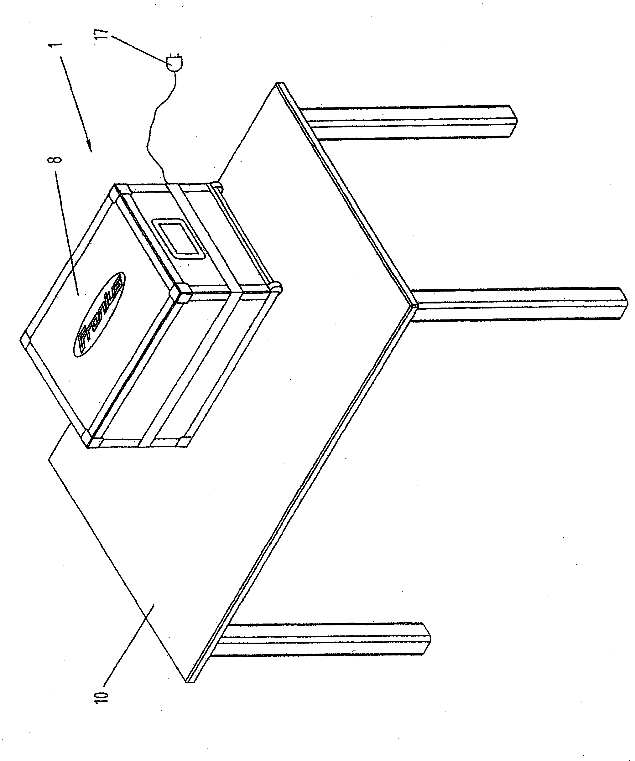
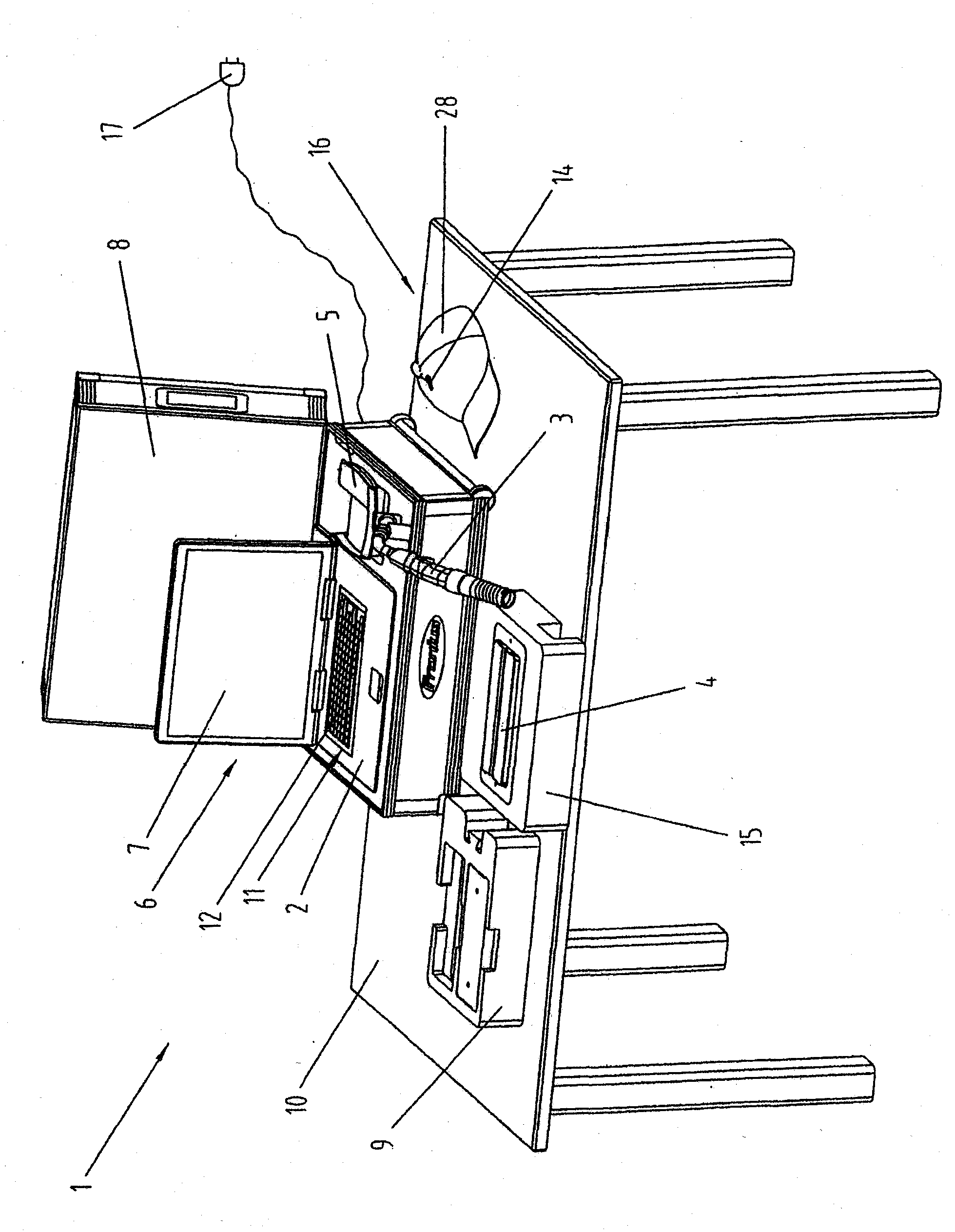
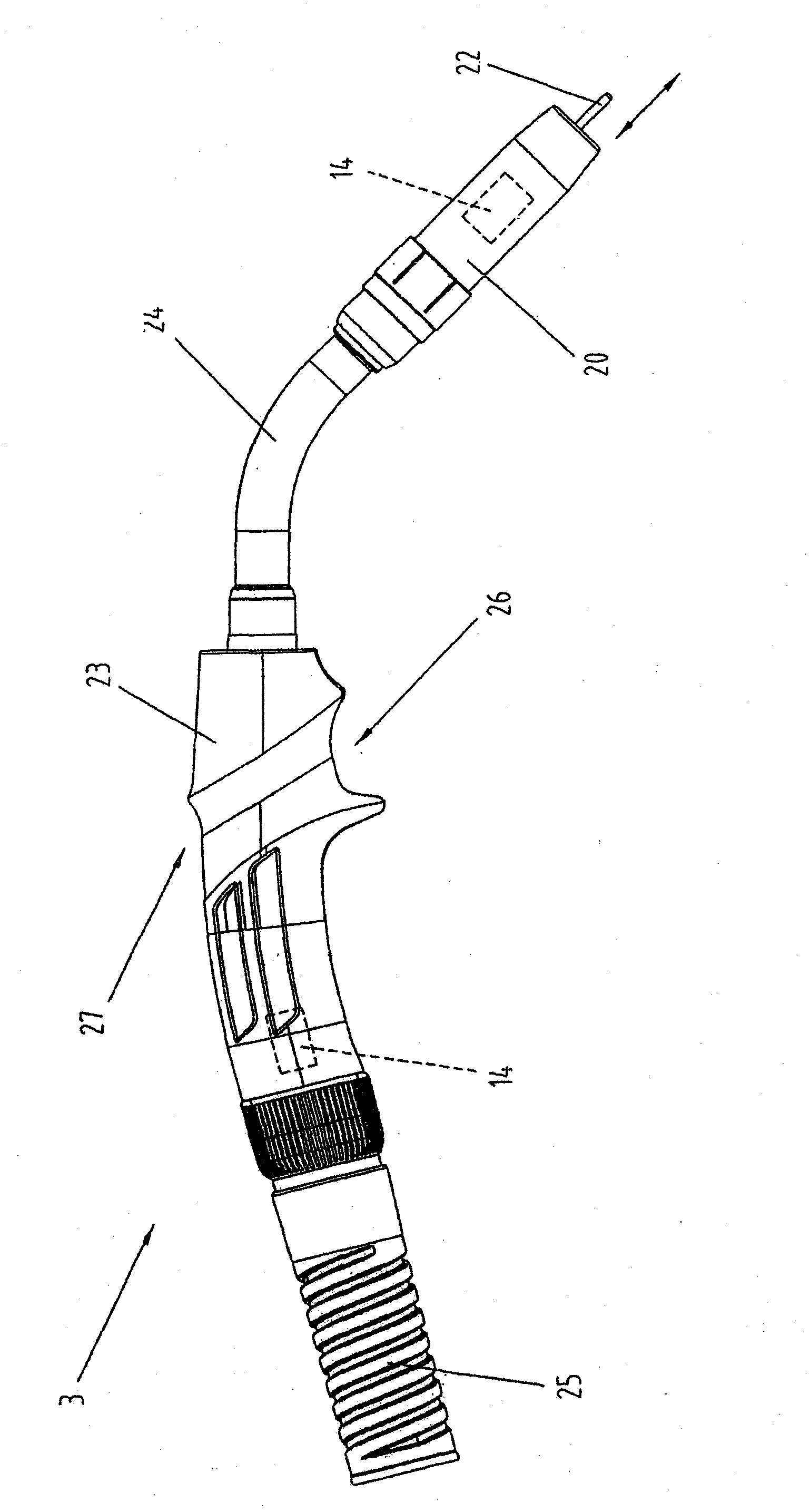
[0047] exist Figure 1 to Figure 12 A device 1 for simulating a welding process is shown in . Basically, it should be noted that in such a device 1 no real welding process takes place, but the welding process is simulated and displayed virtually with the help of software running in the computer 2 . The user is able to practice the welding process with the help of a welding torch 3 available on the market, which is reconfigured for the above-mentioned purpose, ie it enables guiding of the welding torch 3 relative to the workpiece 4 . Such a simulation or practice system offers the advantage that the user can practice the welding process whenever desired without consuming corresponding additional material for the welding process and without workpieces or objects which are subsequently discarded as scrap. Thus, for example, welders can each be trained in a new welding process, or new users can be easily and easily taught a new welding process in a simple manner, before the user ...


PUM


Abstract

The invention relates to a device (1) and a method for simulating a welding process. The device comprises a computer (2) having an input device (11) and an output device (6), a welding torch (3), a magnetic position monitoring device (5) having at least one transmitter (13) and a plurality of sensors (14), a retaining device (15) for a workpiece (4) used for the simulation and a visualization device (16) for generating a two- or three-dimensional image (29) on the output device (6). The retaining device (15) has a recess (18) into which the workpiece (4) can be inserted, at least one transmitter (13) of the position monitoring device (5) being arranged below the recess (18) at as small a distance from the workpiece (4) as possible, and the retaining device (15) being designed as a small, portable box (19) to be placed on a table (10).

Description

technical field [0001] The invention relates to a device for simulating a welding process comprising: a computer with input means and output means; a welding torch; a magnetic position monitoring device having at least one transmitter and a plurality of sensors; A holding device for a workpiece used in a simulation; a vision device for generating a two-dimensional or three-dimensional image on an output device. [0002] Furthermore, the invention relates to a method for performing a simulation of a welding process according to the preambles of claims 17, 18, 23, 24 and 26. Background technique [0003] Various vision welding systems are known. For example in www.simwelder.com A vision welding system is shown above, which is formed from a base element, a welding stand and a workpiece element. A computing unit for computing the welding process and a monitor for displaying the welding process are arranged in the base element. In addition, the welding torch is connected to t...

Claims


Application Information

Patent Timeline
IPC IPC(8): B23K9/00B23K9/095B23K37/04G09B19/00G09B19/24G09B23/06G09B25/02
CPCG09B19/003B23K9/095B23K37/04G09B25/02G09B19/24B23K9/00
Inventor 约瑟夫·克赖因德尔斯蒂芬·格兰塞克
Owner FRONIUS INTERNATIONAL GMBH
Why Eureka
Try Eureka