Magnetic resonance dynamic imaging method

A dynamic imaging and magnetic resonance technology, applied in magnetic resonance measurement, measurement using nuclear magnetic resonance imaging system, and magnetic variable measurement, etc., can solve the problem of incomplete overlapping of motion trajectories, image artifacts, and prolonged scanning sequence completion time. And other issues

Active Publication Date: 2011-06-08
SHANGHAI UNITED IMAGING HEALTHCARE
View PDF4 Cites 9 Cited by
  • Summary
  • Abstract
  • Description
  • Claims
  • Application Information

AI Technical Summary

Problems solved by technology

[0004] Because this method is proposed based on the assumption that the motion track of the object to be measured is periodically repeated, but in fact, the motion tracks of tissues or organs do not completely overlap in different motion cycles, so the images obtained by this method are still Artifacts exist
At the same time, after the previous scan, the MRI scan must wait for the arrival of the next motion cycle before the next scan can be performed. Therefore, the time to complete the scan sequence is extended

Method used


Image

  • Magnetic resonance dynamic imaging method
  • Magnetic resonance dynamic imaging method
  • Magnetic resonance dynamic imaging method

Examples


Embodiment 1

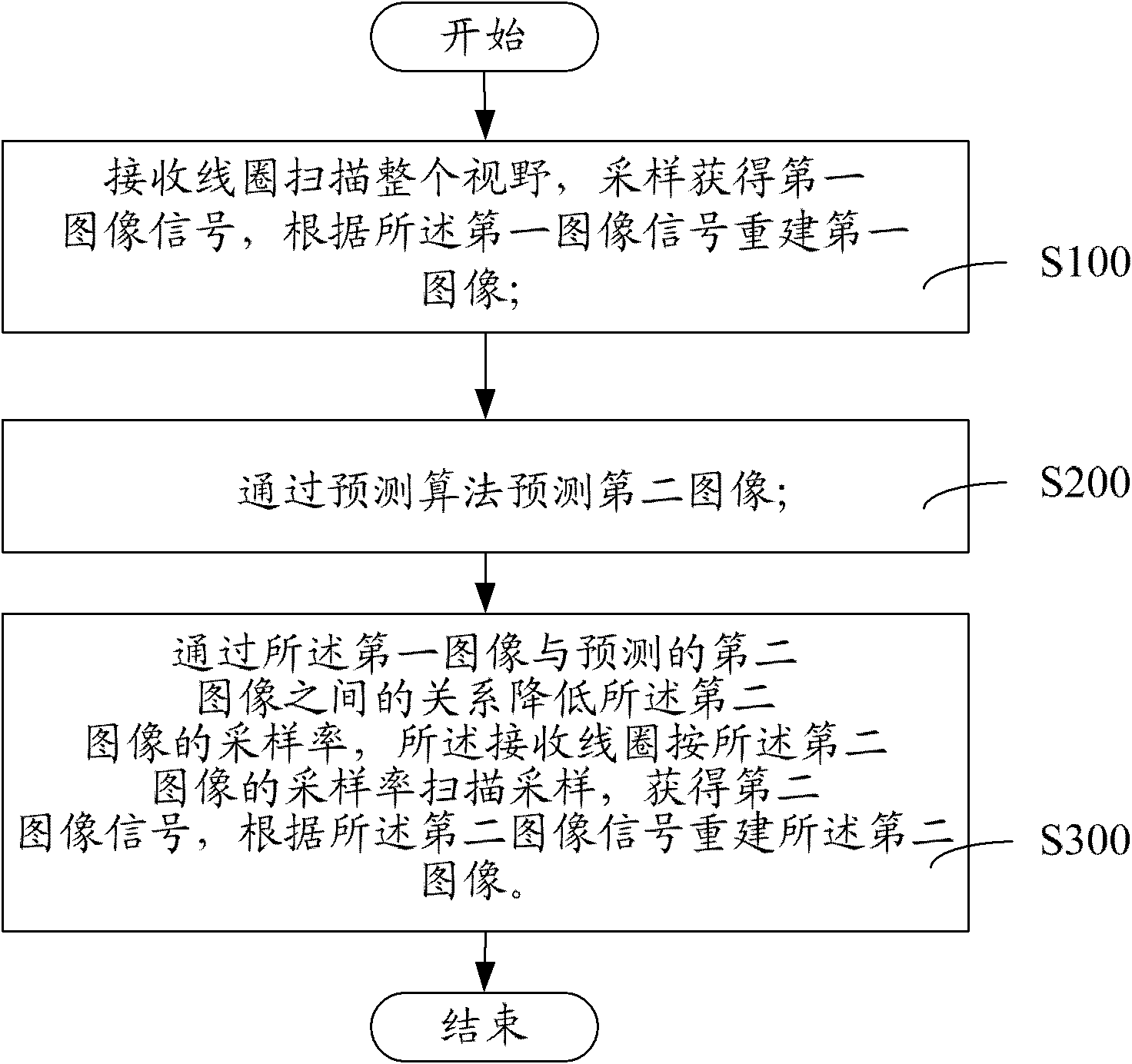
[0034] The first embodiment, when the radio frequency coil is a single coil, such as figure 1 Shown:

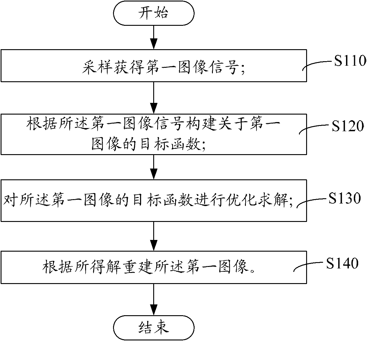
[0035] In step S100, the radio frequency coil scans the entire field of view, samples the first image signal to obtain, and reconstructs the first image according to the first image signal. Step S100 also includes the following steps, such as figure 2 Shown:

[0036] Step S110, sampling to obtain a first image signal. In the magnetic resonance device, the radio frequency coil can be used as the receiving end and the transmitting end of the signal at the same time; the functions of receiving signal and transmitting signal can also be placed on two radio frequency coils respectively. The radio frequency coil with the function of transmitting signal is called the transmitting coil. The radio frequency coil with receiving function is called receiving coil. The radio frequency coil mentioned in this article is mainly aimed at its receiving function. The field of view refers to the...

Embodiment 2

[0081] The second embodiment, when the radio frequency coil is a phased array coil, such as Figure 8 Shown:

[0082] Step S410: Obtain the sensitivity function of each coil in the phased array coil. The phased array coil is composed of multiple coil arrays. The position of each coil in the phased array coil is different, so the imaging area is also different. To synthesize multiple frames of image signals obtained by the phased array coil into one image, the sensitivity function must be used. Step S410 also includes the following steps, such as Picture 9 Shown:

[0083] Step S411, pre-scan the entire field of view, and each coil in the phased array coil obtains a composite image;

[0084] Step S412: Calculate the respective squared images of these composite images, average all the squared images and then take the square root to obtain a frame of square root image f sos ;

[0085] Step S413: Perform fitting optimization on the sensitivity value of each pixel of the square root ima...


PUM


Abstract

The invention relates to a magnetic resonance dynamic imaging method comprising the following steps: sampling by scanning the whole visual field by a radio-frequency coil to acquire a first image signal, and reconstructing a first image according to the first image signal; predicting a second image by a prediction algorithm; and reducing the sampling rate of the second image by the relation between the first image and the predicted second image, scanning and sampling according to the sampling rate of the second image by the radio-frequency coil to acquire a second image signal, and reconstructing the second image according to the second image signal. In the magnetic resonance dynamic imaging method, based on the prior knowledge of slow conversion of a sampled object, the second image is predicted by the prediction algorithm, and the sampling rate is reduced according to the predicted second image, thus reducing the sampling number and reducing the scanning time.

Description

【Technical Field】 [0001] The present invention relates to magnetic resonance, especially a dynamic magnetic resonance imaging method. 【Background technique】 [0002] Magnetic resonance dynamic imaging is a technique often used in medical diagnosis. Due to the movement of tissues or organs, MRI equipment will produce artifacts in the imaging process, which will blur the image, thereby reducing the resolution and diagnostic value of the image. [0003] The traditional gated monitoring technology assumes that the movement trajectory of the object to be measured is repeated periodically, so the movement period of the object to be measured can be measured by the monitor first, and then, it is interrupted at any periodically repeated point in the movement cycle of the object to be measured Type magnetic resonance scanning until the scanning sequence is completed, to obtain a clear image without artifacts. [0004] Because this method is proposed on the assumption that the trajectory of t...

Claims


Application Information

Patent Timeline
IPC IPC(8): A61B5/055G01R33/54
Inventor 寇波邱本胜谢国喜刘新郑海荣张磊
Owner SHANGHAI UNITED IMAGING HEALTHCARE
Why Eureka
Try Eureka