Reducing agent atomization spray gun for selective non-catalytic reduction denitration process

An atomizing spray gun, non-catalytic technology, applied in the direction of spraying devices, liquid spraying devices, chemical instruments and methods, etc., can solve the problems of increasing operating costs, easy generation of liquid droplets, enlarged gun body diameter, etc., to achieve atomization effect Good, simple structure, no consumables

Inactive Publication Date: 2011-06-08
CHINESE RES ACAD OF ENVIRONMENTAL SCI
View PDF3 Cites 35 Cited by
  • Summary
  • Abstract
  • Description
  • Claims
  • Application Information

AI Technical Summary

Problems solved by technology

[0004] The key equipment of the SNCR system is the reducing agent atomizing spray gun. Since the working environment temperature can reach up to 1300°C, the requirements for the material and processing technology of the spray gun are relatively high. At present, the spray guns used in the domestic SNCR system are mainly imported spray guns. The price is high; the atomization form of some spray guns is to set a mixed atomizing nozzle at the end, and the gas and liquid are mixed and atomized at the end. Due to the short contact tim...

Method used


Image

  • Reducing agent atomization spray gun for selective non-catalytic reduction denitration process
  • Reducing agent atomization spray gun for selective non-catalytic reduction denitration process
  • Reducing agent atomization spray gun for selective non-catalytic reduction denitration process

Examples


Embodiment Construction

[0020] The present invention will be further described below in conjunction with the accompanying drawings.

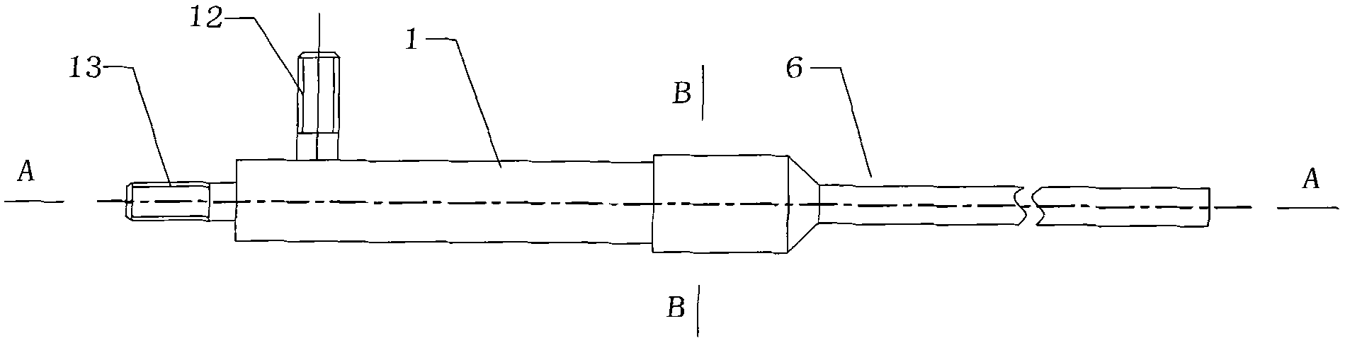
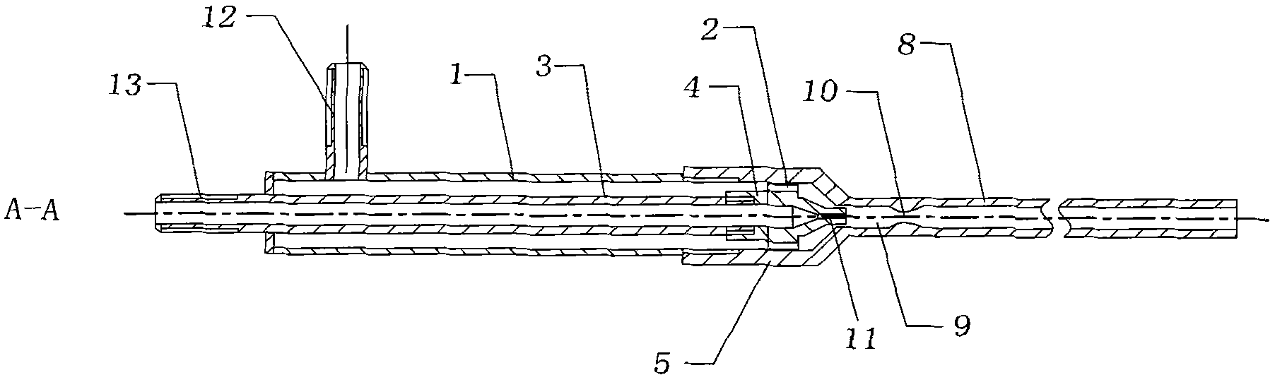
[0021] like Figures 1 to 3 as shown,

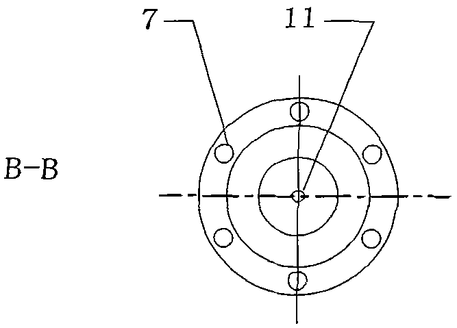
[0022] The reductant atomizing spray gun used for the selective non-catalytic reduction denitrification process of the present invention comprises a gas pipe 1, a liquid pipe 3, a liquid nozzle 4 and a spray pipe 6, the side of the gas pipe 1 is provided with an air inlet port 12, and the liquid pipe One end of 3 protrudes from the gas pipe 1, and a liquid inlet port 13 is provided at this end, and a gas channel is formed between the inner wall of the gas pipe 1 and the outer wall of the liquid pipe 3. The liquid nozzle 4 is threadedly connected to the other end of the liquid pipe 3, and the periphery of the liquid nozzle 4 is provided with a flange 2, and the flange 2 is provided with a plurality of ventilation holes 7; the spray pipe 6 is composed of a connecting part 5 and a pipe body 8 , the connection part 5 is threadedly ...


PUM

PropertyMeasurementUnit
The inside diameter ofaaaaaaaaaa
Outer diameteraaaaaaaaaa

Abstract

The invention provides a reducing agent atomization spray gun for a selective non-catalytic reduction denitration process. The spray gun comprises a gas pipe, a liquid pipe, a liquid nozzle and an injection pipe, wherein the side surface of the gas pipe is provided with a gas inlet interface; one end of the liquid pipe extends out of the gas pipe and is provided with a liquid inlet interface; the liquid nozzle is in threaded connection with the other end of the liquid pipe; the periphery of the liquid nozzle is provided with a flange which is provided with multiple vent holes; the injection pipe consists of a connection part and a pipe body, the connection part is in threaded connection with the gas pipe, and the inner wall of the injection pipe is in contact with the flange of the liquid nozzle; the injection port end of the liquid nozzle enters the pipe body of the injection pipe, and a gap exists between the injection port end and the inner wall of the injection pipe; a mixing nozzle is also arranged in the pipe body of the injection pipe; and a gas-liquid mixing space is formed between the mixing nozzle and the injection port of the liquid nozzle. The spray gun is of a simple structure, low in manufacturing cost and good in atomization effect without producing water drop, and does not have consumable; as the pipe diameter of the part, entering a boiler, of the spray gun is small, the water cooled wall does not need to be reconstructed during installation; and the compressed air or superheated steam can be used as an atomization air source.

Description

technical field [0001] The invention relates to a reducing agent atomizing spray gun used in selective non-catalytic reduction and denitrification process, which is used for reducing the content of nitrogen oxides in coal-fired flue gas. Background technique [0002] With the rapid development of my country's economy, industry and agriculture, the emissions of air pollutants sulfur dioxide and nitrogen oxides have also increased rapidly. As of 2009, my country's sulfur dioxide emissions were 25.9 million tons; nitrogen oxide emissions were about 16 million tons. If no effective nitrogen oxide pollution control measures are taken, my country's nitrogen oxide emissions will reach about 29 million tons in 2020. And in recent years, the concentration of nitrogen oxides in the air of some large cities in my country has exceeded the standard, the environmental capacity of nitrogen oxides has basically been saturated, and some places even produce photochemical smog. [0003] Due ...

Claims


Application Information

Patent Timeline
IPC IPC(8): B01D53/90B01D53/56B05B7/04
Inventor 王凡朱金伟张凡刘宇
Owner CHINESE RES ACAD OF ENVIRONMENTAL SCI
Why Eureka
Try Eureka