Hydraulic clamp capable of tilting vertical and horizontal rolls in air

A clamp and hydraulic technology, which is applied in the field of steel coil hoisting and flipping equipment, can solve the problems of increasing production costs, and achieve the effects of saving production costs, convenient control, and avoiding stalling

Inactive Publication Date: 2011-06-08
宋振才
View PDF6 Cites 4 Cited by
  • Summary
  • Abstract
  • Description
  • Claims
  • Application Information

AI Technical Summary

Problems solved by technology

However, this approach increases production costs

Method used


Image

  • Hydraulic clamp capable of tilting vertical and horizontal rolls in air
  • Hydraulic clamp capable of tilting vertical and horizontal rolls in air
  • Hydraulic clamp capable of tilting vertical and horizontal rolls in air

Examples


Embodiment Construction

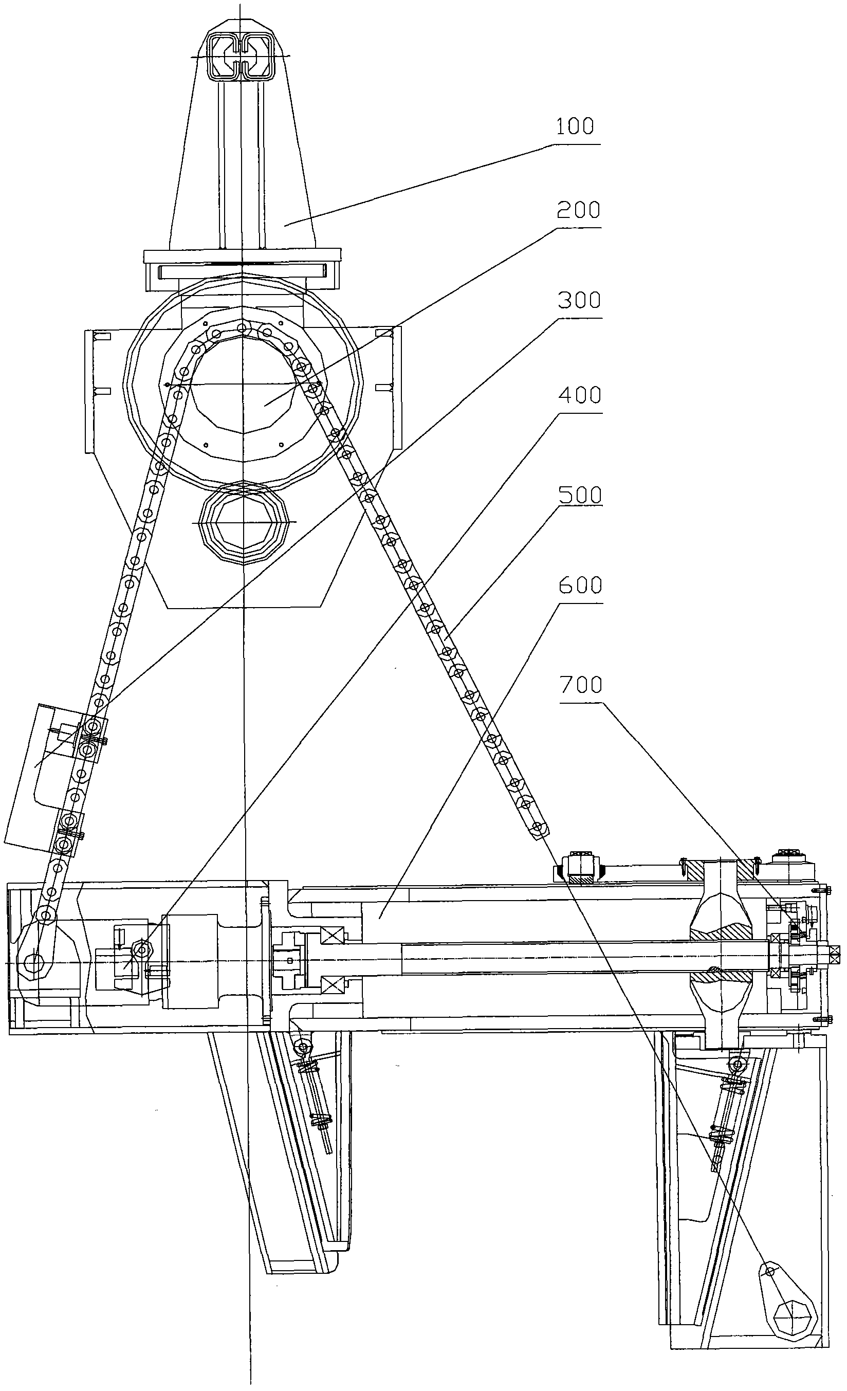
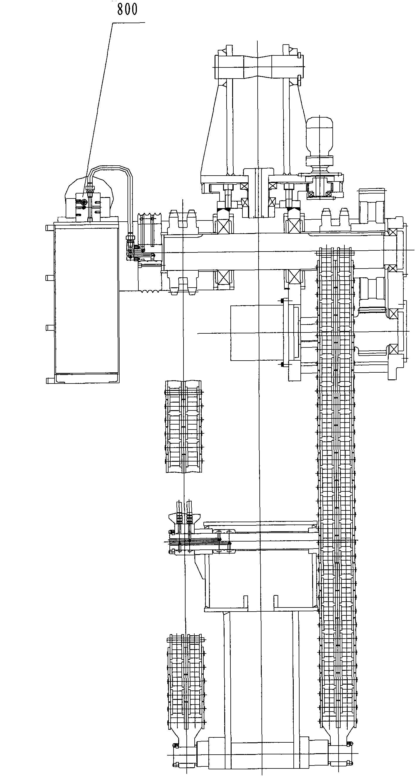
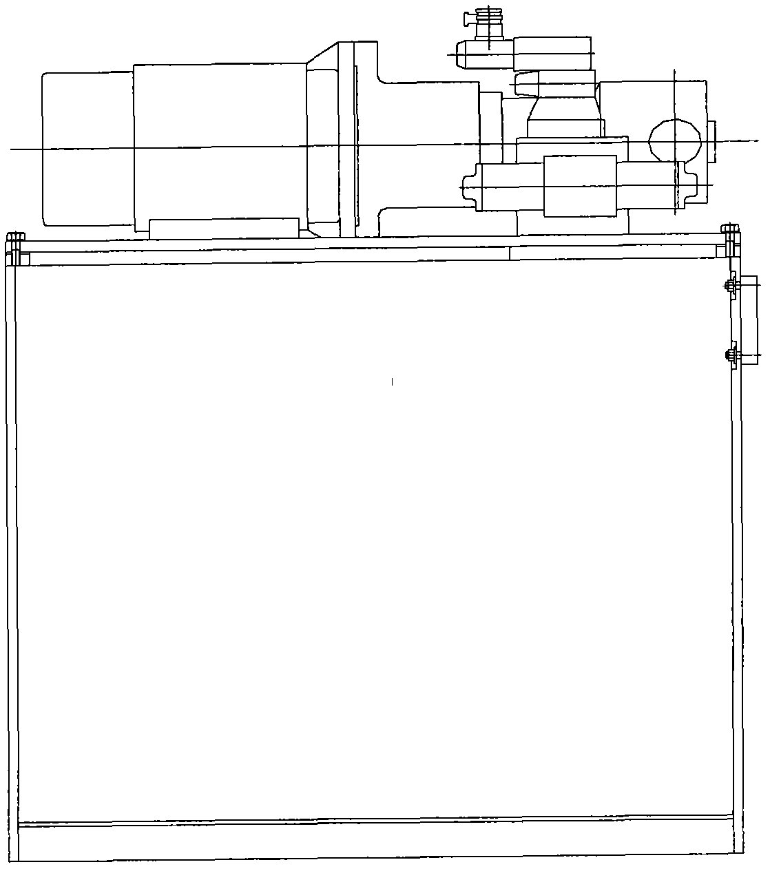
[0027] Clamp overall, such as figure 1 , 2 , as shown in 3:

[0028] hydraulic flip clamp see figure 1 , consisting of a horizontal rotating part 100, a flipping part 200, a clamping part 600, a control part composed of a safety switch 300, a flipping stroke control device 400, and a clamping stroke control device 700, a chain assembly 500 connecting the flipping part and the clamping part, and The hydraulic part 800 is composed. figure 2 is the side view of the clamp, image 3 This is the external view of the clamp hydraulic system.

[0029] Flip parts, such as Figure 4 , 5 Shown:

[0030] The turning part is composed of a hydraulic motor and a reducer 1, a pinion shaft 2, a sprocket 3, a chain 4, a main shaft 5, a large gear 6 and a turning body 7. The hydraulic motor and reducer 1 are directly assembled with the pinion shaft, installed on the lower part of the overturning body 7 through bearings, the large gear 6, and two sprockets 3 are installed on the main shaf...


PUM


Abstract

The invention relates to a hydraulic clamp capable of tilting vertical and horizontal rolls in air, which comprises a horizontal rotating part, a tilting part, a clamp part, a hydraulic part, a chain assembly and a control part. The hydraulic air tilting clamp provided by the invention can hang steel rolls in the air and tilt the steel rolls from horizontal rolls into vertical rolls and vice versa, enhances the production efficiency, saves the cost and improves the convenience and safety of the operation through the action of the control part.

Description

technical field [0001] The invention relates to a device for hoisting and turning over steel coils. Background technique [0002] There are generally two states for the storage of steel coils, that is, the horizontal coil state and the vertical coil state. During the production and transportation of steel coils, it is necessary to adjust the placement state of the steel coils according to the actual situation. For example, steel coils are rolled off the production line horizontally but need to be loaded in vertical coils, and the steel coils need to be turned over during this process. In order to solve the technical problem of coil overturning, vertical coil tongs, horizontal coil tongs and ground coilers are often used to cooperate with each other in the prior art. However, this approach increases production costs. Contents of the invention [0003] Aiming at the technical problems existing in the prior art, the present invention provides a new type of tongs hung under...

Claims


Application Information

Patent Timeline
Patent Type & Authority Applications(China)
IPC IPC(8): B66C1/12B66C1/44B66C13/08
Inventor 宋振才
Owner 宋振才
Why Eureka
Try Eureka