Glass preform drawing apparatus

A technology of stretching device and preform, which is applied in glass forming, glass reshaping, glass production, etc., to achieve the effect of device simplification

Active Publication Date: 2014-09-24
SHIN ETSU CHEM CO LTD
View PDF7 Cites 0 Cited by
  • Summary
  • Abstract
  • Description
  • Claims
  • Application Information

AI Technical Summary

Problems solved by technology

Therefore, the outer diameter of the drawn glass rod may be larger than the predetermined value

Method used


Image

  • Glass preform drawing apparatus
  • Glass preform drawing apparatus

Examples


Embodiment 1

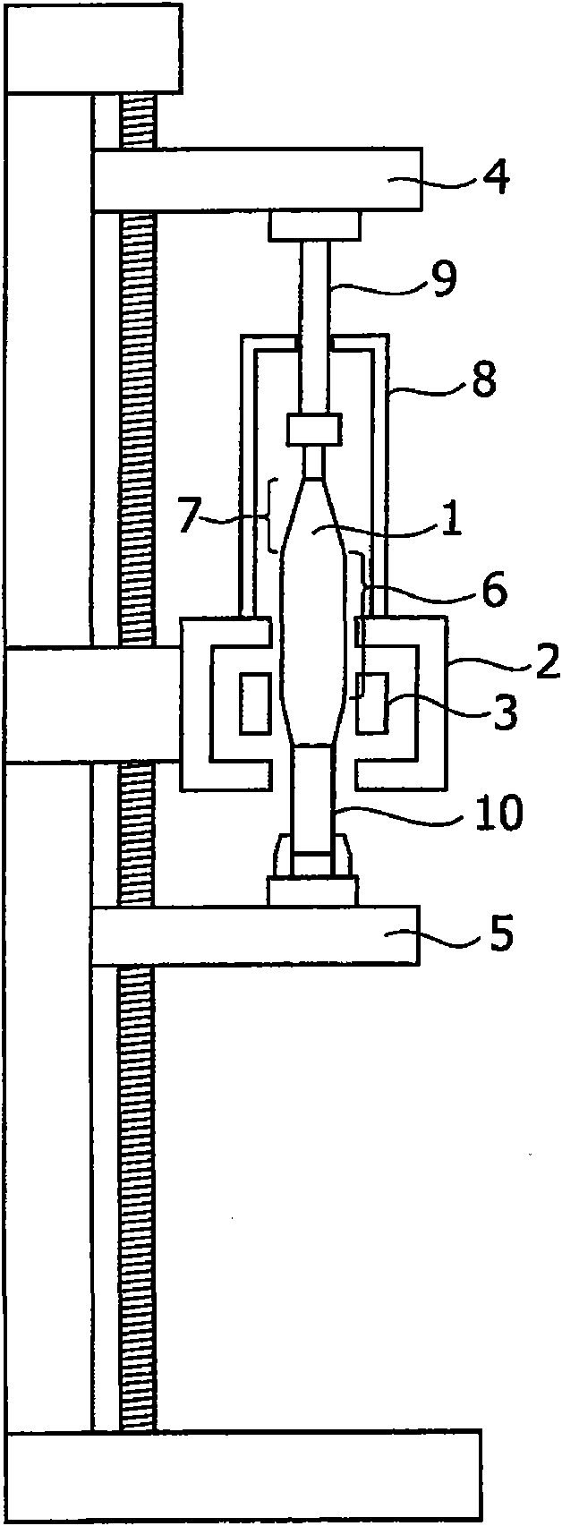
[0037] use figure 1In the shown device, the glass preform 1 for the optical fiber preform is stretched to a target outer diameter d=120mm. The glass preform 1 includes an effective portion having an average outer diameter of 170.5 mm, a length of 1000 mm, and tapered portions of approximately 300 mm at both ends of the effective portion. The material of the top chamber 8 is quartz glass. In the stretching step, the inside of the heating furnace 2 was kept under a nitrogen atmosphere at a temperature of 2300K.

[0038] Determine the stretching conditions according to the following formula:

[0039] V 2 =V 1 ×(D / d) 2

[0040] Among them, V 1 is the feeding speed of the glass preform (V 1 =10mm / min); V 2 is the extraction speed of the glass rod; D is the outer diameter of the stretched part of the glass preform.

[0041] In the glass rod obtained by stretching the effective portion of the glass preform, the maximum outer diameter near the end of stretching was 120.8mm,...


PUM

PropertyMeasurementUnit
diameteraaaaaaaaaa
wavelengthaaaaaaaaaa
diameteraaaaaaaaaa

Abstract

The present invention provides a glass preform drawing apparatus capable of feeding a glass preform into a heating furnace at a predetermined feed speed and producing a glass rod having a uniform diameter. Specifically, the present invention provides a glass preform stretching device for producing a glass rod with a desired outer diameter by heating and stretching a glass preform, wherein, at the normal operating temperature T (K ), the top chamber is transparent at a wavelength λ (μm) represented by the following formula: λ=2898 / T.

Description

technical field [0001] The present invention relates to a glass preform drawing apparatus for producing glass preforms such as optical fiber preform ingots in a heating furnace and then drawing the heated preforms to a desired outer outside diameter of the glass rod. Background technique [0002] In an apparatus for producing a glass rod having a desired outer diameter by heating and stretching a glass preform typified by an optical fiber preform ingot or the like, according to Japanese Patent Application Publication Nos. 11-147731, 11-060259, 06- 256034 and 11-209137, some devices include a glass preform container called a top chamber in the upper part of the device. [0003] figure 2 is a schematic diagram of a glass preform stretching apparatus including a top chamber. [0004] The glass preform 101 is heated by a heater 103 provided inside the heating furnace 102 . While the glass preform 101 is fed into the heating furnace through the feeding mechanism 104, the glas...

Claims


Application Information

Patent Timeline
Patent Type & Authority Patents(China)
IPC IPC(8): C03B37/025
CPCC03B23/043C03B37/0124Y02P40/57
Inventor 乙坂哲也
Owner SHIN ETSU CHEM CO LTD
Why Eureka
Try Eureka