Steam generator

A steam generator and steam technology, applied in the field of steam generators of steam mops, can solve the problems of insufficient utilization of heat energy, reduced thermal efficiency of steam generators, insufficient utilization of heat energy, etc., and achieve high efficiency.

Inactive Publication Date: 2011-06-08
NINGBO JUSTICE ENG PLASTIC MOULD CO LTD
View PDF5 Cites 17 Cited by
  • Summary
  • Abstract
  • Description
  • Claims
  • Application Information

AI Technical Summary

Problems solved by technology

[0002] Existing steam generators for steam mops usually have a single-inlet and single-outlet coil structure, that is, a single port enters water and the other port exits vaporized steam, and the coil is integrally connected with the heat exchanger and the heating element or It is to directly make grooves and holes similar to coils inside the heat exchange body. The coils are respectively connected to the water source and the steam outlet. , the disadvantage of this structure is that the coils in the heat exchange body are connected in series, and the

Method used


Image

  • Steam generator
  • Steam generator
  • Steam generator

Examples


Embodiment Construction

[0015] A specific embodiment of the present invention will be described in detail below in conjunction with the accompanying drawings, but it should be understood that the protection scope of the present invention is not limited by the specific embodiment.

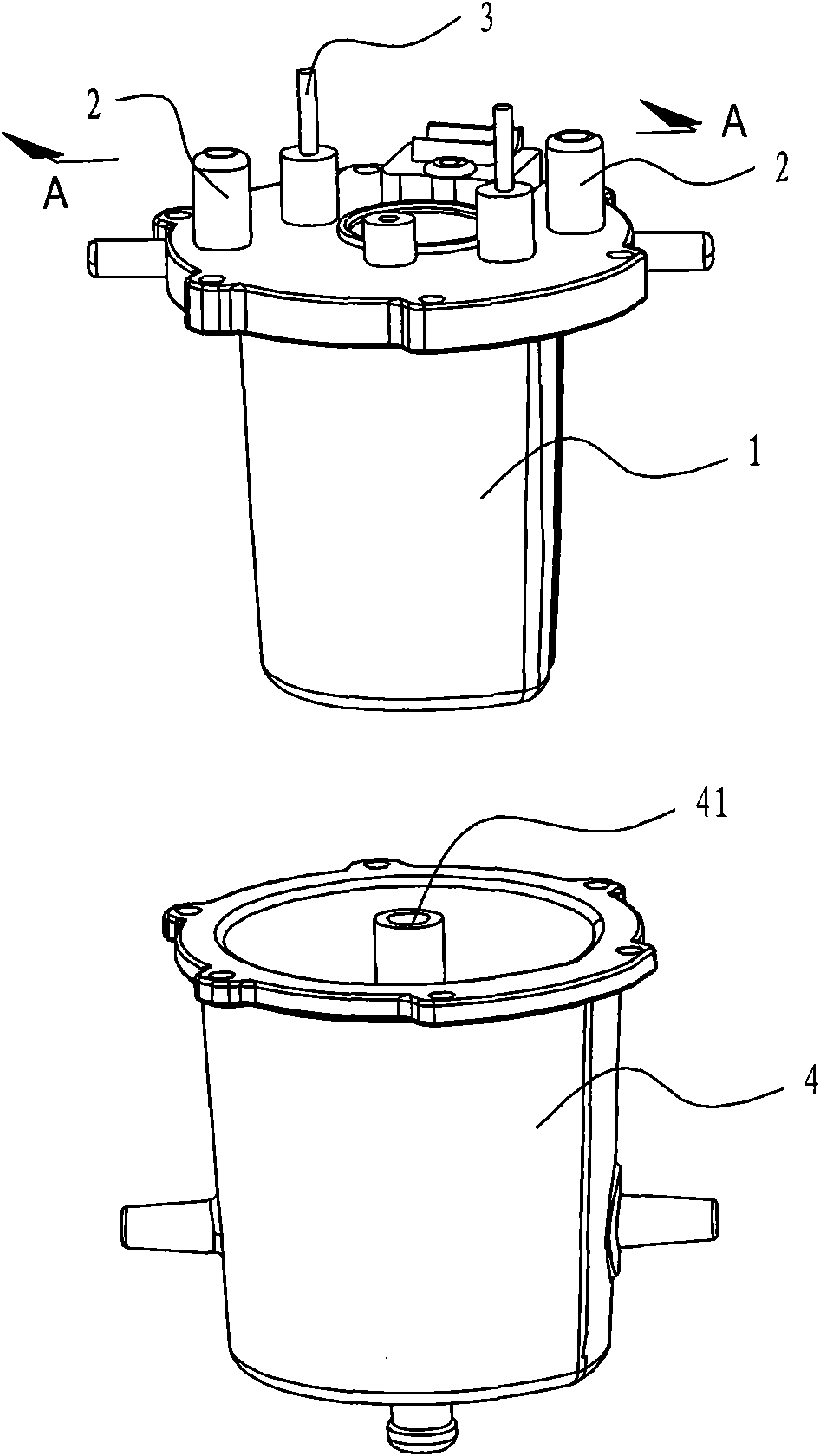
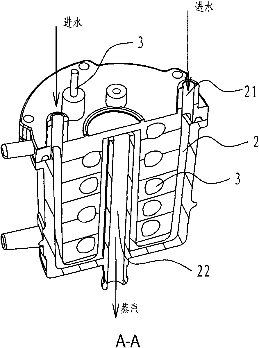
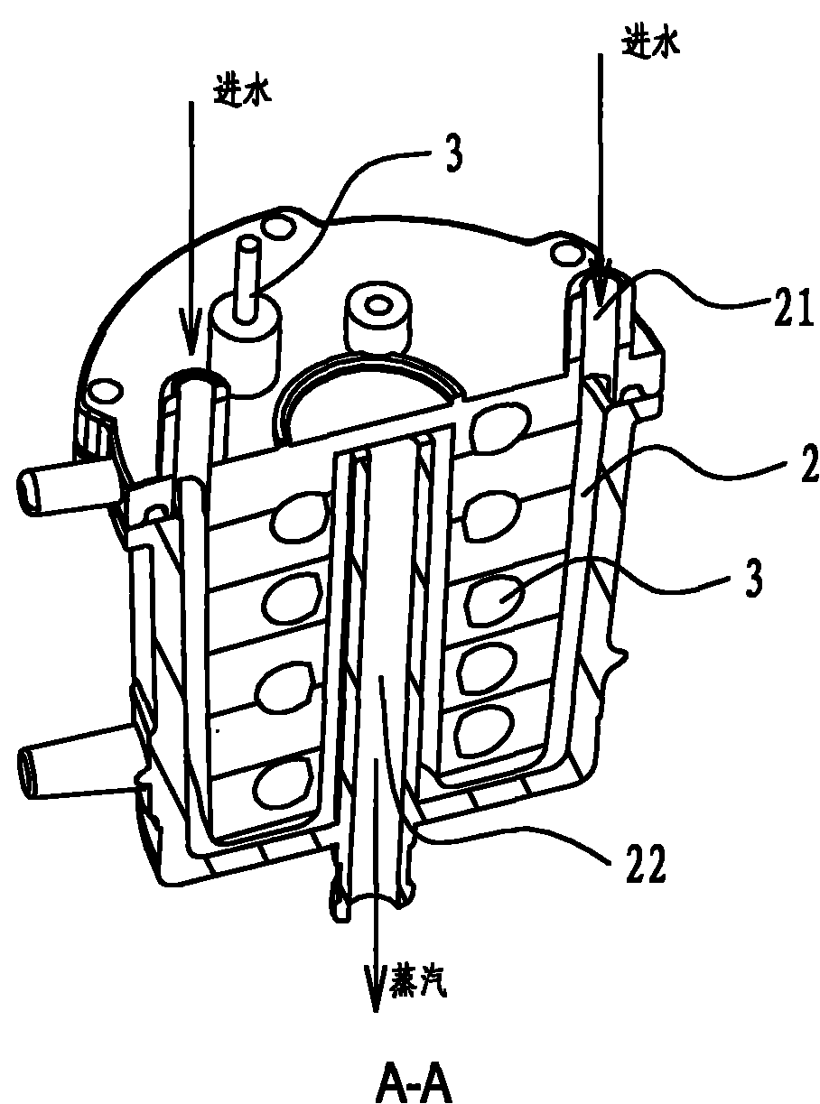
[0016] Such as Figure 1-2 As shown, the steam generator of the present invention is used in a steam mop, and includes a steam generating chamber made of a coiled pipe 2 and a heat exchanger 1 and an electric heater 3, such as figure 2 As shown, the electric heater 3 is composed of an electric heating tube spirally wound into a column (or inverted "U" shape, not shown in the figure), and the heat exchanger 1 is a conical structure (or cylindrical, not shown in the figure). out), its diameter is adapted to the shape of the electric heater (this design can effectively improve the heat exchange efficiency), the heat exchange body 1 is integrally formed with the electric heater 3 through aluminum die-casting and the electric ...


PUM


Abstract

The invention discloses a steam generator which is used in a steam mop, comprising a steam generating cavity composed of coil pipes, a heat exchange body and an electric heater, wherein the heat exchange body is integrally formed with the electric heater by aluminum die-casting and completely wraps up the electric heater, the coil pipe consists of through holes inside the heat exchange body, the electric heater is composed of helically-winded columnar electric heating pipes or reversed U-shaped pipes, water inlets of the coil pipe are symmetrically arranged relative to the axis of the heat exchange body so as to form a double-inlet structure, two coil pipes extend, along the outer side of the electric heater, to the lower end of the electric heater respectively, then turn into a space surrounded by the electric heater and extend once again to be close to the upper end of the electric heater for being converged, the heat exchange body is externally sleeved with a heat-insulated protective casing, the middle part of the heat-insulated protective casing is provided with a steam pipe sleeved to a coil pipe converging pipe, and the steam generated by vaporization of water entering through the water inlet is discharged through the steam pipe. By arranging a coil pipe structure with double water inlets and single outlet, the heat of the electric heater is uniformly absorbed in order to realize high efficiency of the steam generator.

Description

technical field [0001] The invention relates to a steam generator, in particular to a steam generator for a steam mop. Background technique [0002] Existing steam generators for steam mops usually have a single-inlet and single-outlet coil structure, that is, a single port enters water and the other port exits vaporized steam, and the coil is integrally connected with the heat exchanger and the heating element or It is to directly make grooves and holes similar to coils inside the heat exchange body. The coils are respectively connected to the water source and the steam outlet. , the disadvantage of this structure is that the coils in the heat exchange body are connected in series, and the coils in the heat exchange body located on both sides of the heating body are always in a state of large temperature difference due to the series connection, and the higher temperature side The heat energy of the heat exchanger cannot be fully utilized, especially near the inlet of the w...

Claims


Application Information

Patent Timeline
IPC IPC(8): F22B1/28A47L13/22
Inventor 张瑞江
Owner NINGBO JUSTICE ENG PLASTIC MOULD CO LTD
Why Eureka
Try Eureka