Composite dielectric protective film of plasma display panel (PDP) and preparation method thereof
A composite medium and display panel technology, which is applied in the manufacture of tubes/lamp screens, discharge tubes, electrical components, etc., can solve problems such as unstable oxides, reduced ignition voltage, and difficult storage, so as to reduce production costs and ignition voltage , the effect of improving the service life
- Summary
- Abstract
- Description
- Claims
- Application Information
AI Technical Summary
Problems solved by technology
Method used
Image
Examples
Embodiment 1
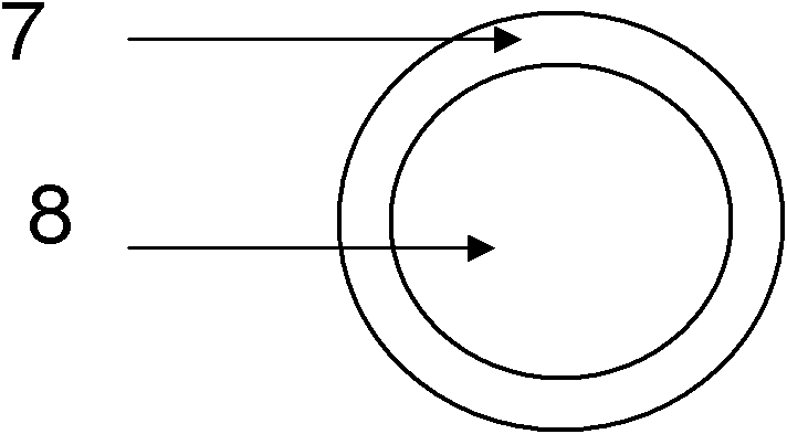
[0048] Select CaO particles with an average particle size of 1-2 μm and place them in the crucible of a thermal evaporation furnace. The crucible is equipped with a stirring device. The evaporation furnace uses Mg as the evaporation source. O 2 As a carrier gas, thermal evaporation coating is carried out, and when MgO with a thickness of 50nm is formed on the surface of CaO, the coating is stopped, and crystal particles with a core-shell structure are prepared.
[0049] Put the crystal particles in the carrier solvent cellulose ether, and form a uniformly dispersed slurry after being punctured. Use a coating machine to evenly disperse the slurry on the surface of the medium layer. After drying at 150°C for 30 minutes, place it in a sintered In the furnace, it is sintered at 550°C to form a transparent composite dielectric protective film.
Embodiment 2
[0051] Select SrO particles with an average particle size of 1-2 μm and place them in the crucible of a thermal evaporation furnace. The crucible is equipped with a stirring device. The evaporation furnace uses Mg as the evaporation source. O 2 As the carrier gas, thermal evaporation coating is carried out, and when MgO with a thickness of 50nm is formed on the surface of SrO, the coating is stopped, and crystal particles with a core-shell structure are prepared.
[0052] Put the crystal particles in the carrier solvent cellulose ether, and form a uniformly dispersed slurry after being punctured. Use a coating machine to evenly disperse the slurry on the surface of the medium layer. After drying at 150°C for 30 minutes, place it in a sintered In the furnace, it is sintered at 550°C to form a transparent composite dielectric protective film.
Embodiment 3
[0054] Select ZnO particles with an average particle size of 1-2 μm and place them in the crucible of a thermal evaporation furnace. The crucible is equipped with a stirring device. The evaporation furnace uses Mg as the evaporation source. O 2 As the carrier gas, thermal evaporation coating is carried out, and when MgO with a thickness of 50nm is formed on the surface of ZnO, the coating is stopped, and crystal particles with a core-shell structure are prepared.
[0055] Put the crystal particles in the carrier solvent cellulose ether, and form a uniformly dispersed slurry after being punctured. Use a coating machine to evenly disperse the slurry on the surface of the medium layer. After drying at 150°C for 30 minutes, place it in a sintered In the furnace, it is sintered at 550°C to form a transparent composite dielectric protective film.
PUM
| Property | Measurement | Unit |
|---|---|---|
| viscosity | aaaaa | aaaaa |
| diameter | aaaaa | aaaaa |
| thickness | aaaaa | aaaaa |
Abstract
Description
Claims
Application Information
 - R&D
- Intellectual Property
- Life Sciences
- Materials
- Tech Scout
- Unparalleled Data Quality
- Higher Quality Content
- 60% Fewer Hallucinations
Browse by: Latest US Patents, China's latest patents, Technical Efficacy Thesaurus, Application Domain, Technology Topic, Popular Technical Reports.
© 2025 PatSnap. All rights reserved.Legal|Privacy policy|Modern Slavery Act Transparency Statement|Sitemap|About US| Contact US: help@patsnap.com


