Cuff for blood pressure measuring device and blood pressure measuring device provided with same

A technology for information measurement and blood pressure, applied in vascular assessment, cardiac catheterization, etc., can solve the problems of cumbersome trachea handling, cuff connection trachea obstruction, etc., and achieve the effect of small operability and portability

Active Publication Date: 2011-06-08
OMRON HEALTHCARE CO LTD
View PDF5 Cites 9 Cited by
  • Summary
  • Abstract
  • Description
  • Claims
  • Application Information

AI Technical Summary

Problems solved by technology

[0016] However, when the structure disclosed in JP-A-3-85138 is adopted, the trachea connecting the cuff and the main body becomes an obstacle during measurement, and the trachea is troublesome to handle during storage.

Method used


Image

  • Cuff for blood pressure measuring device and blood pressure measuring device provided with same
  • Cuff for blood pressure measuring device and blood pressure measuring device provided with same
  • Cuff for blood pressure measuring device and blood pressure measuring device provided with same

Examples


no. 1 approach

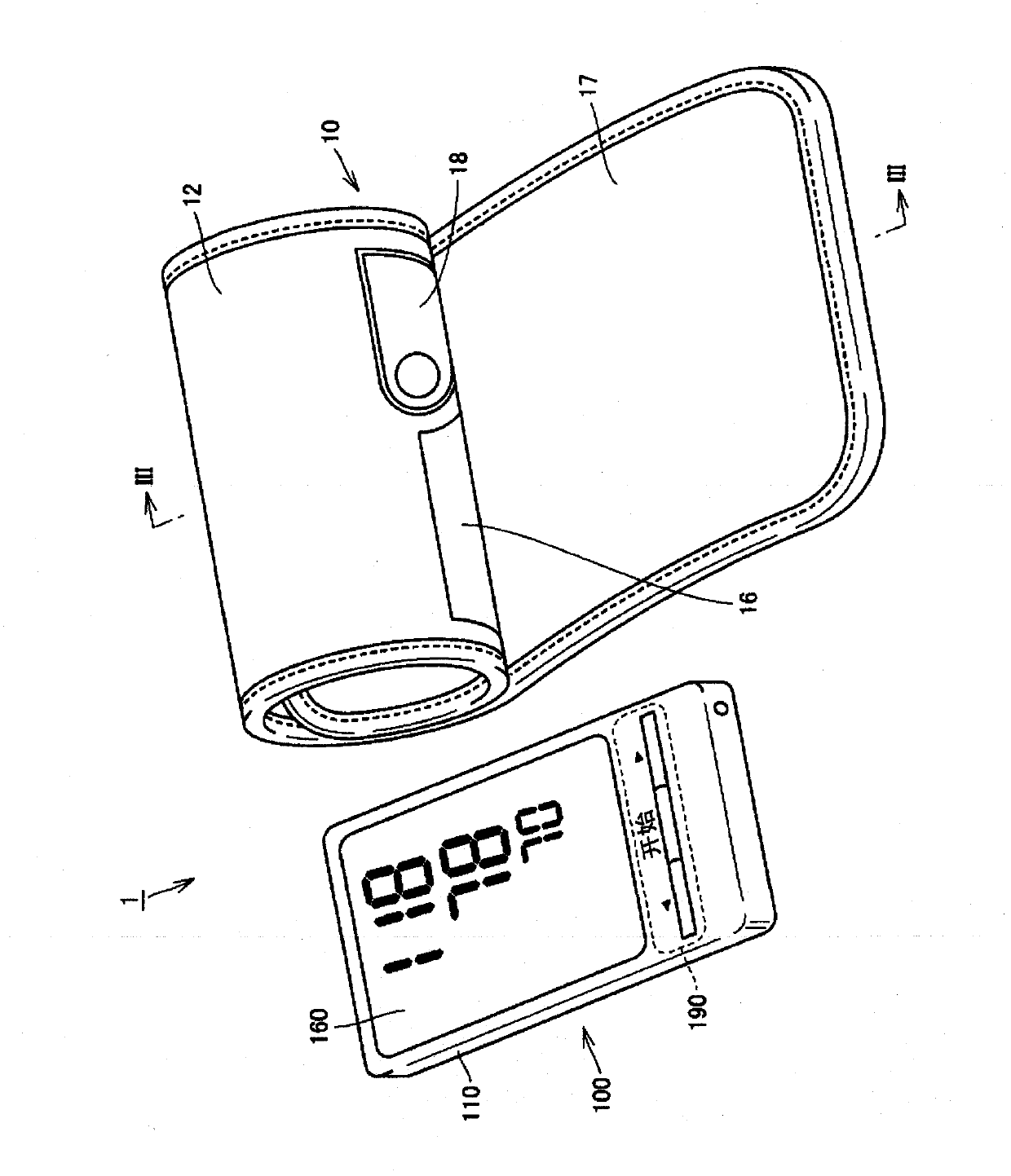
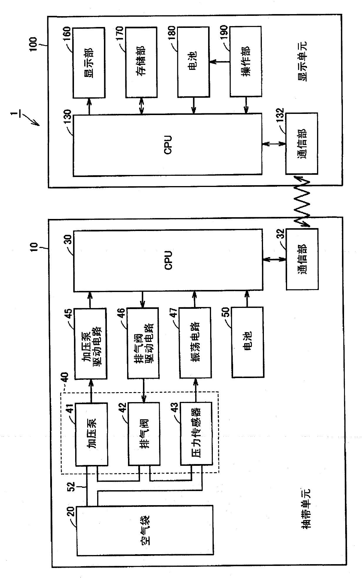
[0051] figure 1 It is a perspective view showing the appearance structure of the sphygmomanometer according to the first embodiment of the present invention, figure 2 yes means figure 1 A block diagram showing the structure of the functional modules of the sphygmomanometer. in addition, image 3 is along figure 1 A sectional schematic diagram of the cuff unit shown on line III-III, Figure 4 yes figure 1 It is a perspective view of the shown cuff unit with the cover removed. First, refer to the above Figure 1 to Figure 4 , and the structure of the sphygmomanometer and the sphygmomanometer cuff included in the sphygmomanometer according to the first embodiment of the present invention will be described.

[0052] Such as figure 1 As shown, the sphygmomanometer 1 of the present embodiment has a cuff unit 10 and a display unit 100 that are separated and configured independently. The cuff unit 10 is configured in a ring shape in which a slit extending in the axial direct...

no. 2 approach

[0080] Figure 8 It is a perspective view showing the appearance structure of a sphygmomanometer according to a second embodiment of the present invention, Figure 9 yes Figure 8 A schematic cross-sectional view of the cuff unit shown. Below, refer to Figure 8 with Figure 9 , and the structure of the sphygmomanometer and the sphygmomanometer cuff included in the sphygmomanometer according to the second embodiment of the present invention will be described. In addition, the same parts as those of the sphygmomanometer of the first embodiment and the sphygmomanometer cuff included in the sphygmomanometer are denoted by the same reference numerals, and description thereof will not be repeated here.

[0081] Such as Figure 8 with Figure 9As shown, the sphygmomanometer 1 of the present embodiment is different from the sphygmomanometer 1 and the cuff unit 10 of the first embodiment described above in configuration. In the cuff unit 10 of the present embodiment, the ring m...

no. 3 approach

[0085] Figure 10 It is a perspective view showing the appearance structure of a sphygmomanometer according to a third embodiment of the present invention, Figure 11 yes means Figure 10 A block diagram showing the structure of the functional modules of the sphygmomanometer. in addition, Figure 12 yes means Figure 10 A perspective view of the detailed structure of the cuff unit shown, Figure 13 is along Figure 12 A schematic cross-sectional view of the cuff on line XIII-XIII shown in . in addition, Figure 14 yes means Figure 12 A schematic top view of the structure of the fastening length adjustment mechanism shown. First, refer to Figure 10 ~ Figure 14 , and the structure of the sphygmomanometer and the sphygmomanometer cuff included in the sphygmomanometer according to the third embodiment of the present invention will be described. In addition, the same parts as those of the sphygmomanometer of the first embodiment described above and the sphygmomanometer ...


PUM


Abstract

Disclosed is a blood pressure meter provided with a cuff unit (10) and a display unit. The cuff unit (10) comprises an air bag (20) for compressing the upper arm, a flexible collar (24) that is positioned outside the air bag (20) and is formed in a ring shape to encircle the upper arm, and an outer cover (12) that encloses the air bag (20) and the collar (24). On the outer surface of the collar (24) are disposed a pressurizing pump (41) and an exhaust valve that cause the air bag (20) to expand or contract, a pressure sensor (43) that detects the internal pressure of the air bag (20), and a battery (50) that serves as a power source. The outer cover (12) encloses all of these. The display unit is provided with a display part, an operating part and a power source part. The cuff unit (10) and the display unit are each provided with a communication part, and wireless communication is performed via these communication parts. Such a configuration enables the construction in a small size ofa blood pressure meter having excellent handling ability and portability.

Description

technical field [0001] The present invention relates to a blood pressure information measuring device cuff used to be worn on a site to be measured, and a blood pressure information measuring device including the blood pressure information measuring device cuff. Background technique [0002] Obtaining the blood pressure information of the subject is very important for understanding the health status of the subject. In recent years, not only systolic blood pressure, diastolic blood pressure, etc., which have been widely recognized as useful indicators, but also attempts to obtain cardiac load and arterial stiffness by obtaining the pulse wave of the subject changes etc. The blood pressure information measuring device is a device for obtaining these indicators for health management based on the obtained blood pressure information, and it is expected to be further applied in fields such as early detection, prevention, and treatment of circulatory system diseases. In addition,...

Claims


Application Information

Patent Timeline
Patent Type & Authority Applications(China)
IPC IPC(8): A61B5/022
CPCA61B5/02141A61B5/02233
Inventor 佐野佳彦有贺裕恭上坂知里大西喜英田中孝英
Owner OMRON HEALTHCARE CO LTD
Why Eureka
Try Eureka