Method for predicting the dynamic behaviour of an aircraft structure

A dynamic performance, aircraft technology, applied in the direction of measuring vibration, rigid supports of machines/engines, bearing components, etc., can solve the problem of not having any method to accurately predict vibration frequency and vibration amplitude, etc.

Active Publication Date: 2011-06-08
AIRBUS OPERATIONS GMBH
View PDF6 Cites 9 Cited by
  • Summary
  • Abstract
  • Description
  • Claims
  • Application Information

AI Technical Summary

Problems solved by technology

[0010] - So far, there is no method of accurately predicting the frequency and magnitude of vibrations induced by engines or other rotating devices on the fuselage of new aircraft; these vibrations are evaluated during test flights of the aircraft at a stage where any modifica...

Method used


Image

  • Method for predicting the dynamic behaviour of an aircraft structure
  • Method for predicting the dynamic behaviour of an aircraft structure
  • Method for predicting the dynamic behaviour of an aircraft structure

Examples


Embodiment Construction

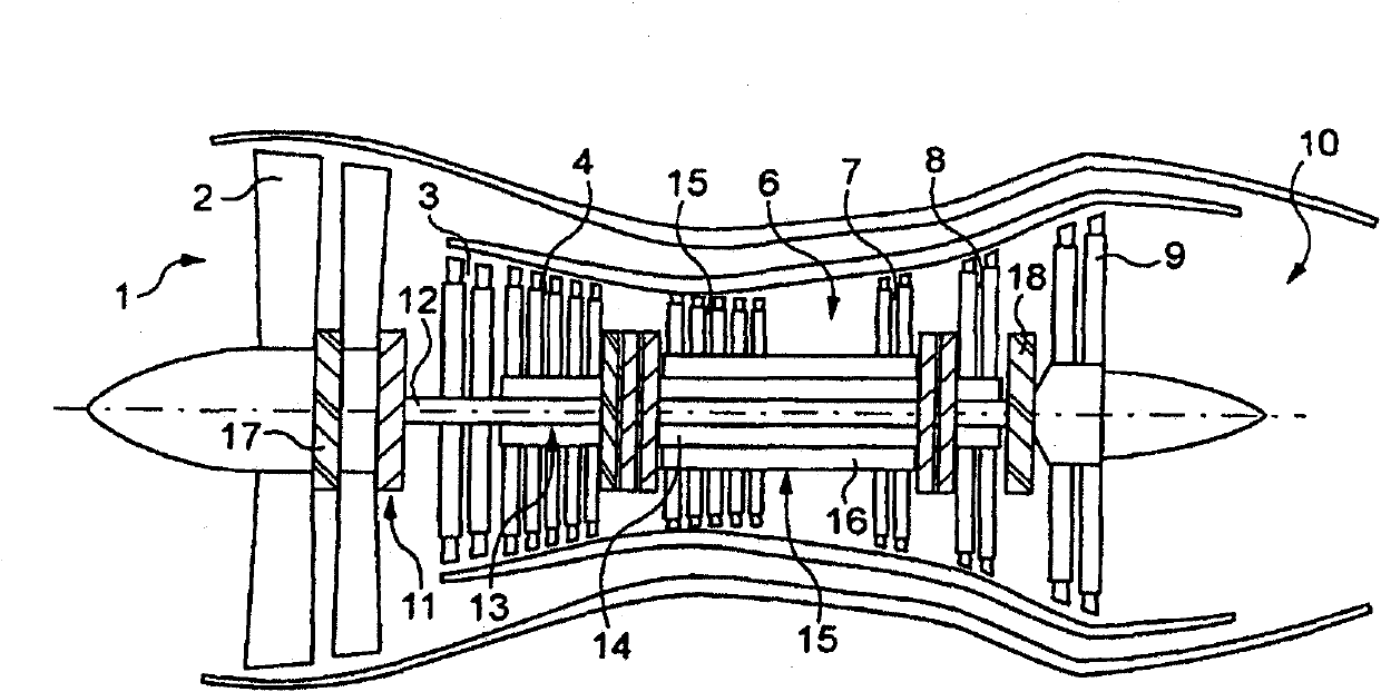
[0074] Certain airplanes or other known aircraft include engines with rotors, such as twin-body or triple-body turbojets. figure 1 A three-body turbojet engine is shown, generally comprising an air inlet 1, a compression zone comprising a large diameter blower 2 and several stages of compressors 3, 4, 5, a combustion chamber 6, comprising several stages of a turbine 7, 8, the gas expansion zone of 9, and the injection pipe 10. This turbojet engine consists of:

[0075] - a first rotor 11 called low-pressure rotor, which includes the blower 2, the low-pressure compressor 3, the low-pressure turbine 9 and the first shaft 12 supporting the above-mentioned elements;

[0076] - the second rotor 13, called the intermediate pressure rotor, comprising the intermediate pressure compressor 4, the intermediate pressure turbine 8, and the second shaft 14 supporting the aforementioned elements;

[0077] - A third rotor 15 , called the high-pressure rotor, comprising the high-pressure compr...


PUM


Abstract

The invention relates to a method for predicting the dynamic behaviour of an aircraft structure, said aircraft comprising at least one rotary device including at least one rotor (11) guided in rotation by at least one fixed-bracket bearing (17, 18) containing a shock-absorbing fluid film (24), wherein said method comprises using a global digital model of the aircraft structure including a basic digital model of each rotary device, generating a non-linear digital model of each shock-absorbing film (preferably by developing a cavitation-free model and a model with cavitation), integrating the model of each shock-absorbing film with the global model, applying interference to at least one rotor of a rotary device, calculating the vibration frequency of at least one rotor of each rotary device and the corresponding frequency of the vibrations generated in a critical portion of the aircraft structure.

Description

technical field [0001] The present invention relates to a method of predicting the dynamic performance of the structure of an aircraft, which method can predict the vibrations to which at least a part of the structure is subjected due to vibrations caused by certain rotating devices of the aircraft, such as rotors of engines, generators, etc., in order to avoid or Dampen those vibrations. Background technique [0002] On an aircraft equipped with an engine with a rotor (jet propulsion, turbojet, turboprop, etc.), any imbalance in the rotating elements of the engine generates vibrations which are transmitted to the casing of the engine and to the structure of the aircraft spread until the fuselage. Subsequent vibration of the airframe impairs passenger comfort, fatigues the aircraft's structure, and may compromise safety by making it difficult to read flight instruments. [0003] Aircraft engines with rotors generally comprise one or several rotors, each rotor comprising a ...

Claims


Application Information

Patent Timeline
IPC IPC(8): F16C27/04G01H1/00
CPCF16C39/04F16C27/04F16C35/077F01D25/164Y02T10/82G01H1/006F16C19/06F16C27/045F16C2360/23
Inventor J·斯凯利T·P·武黄
Owner AIRBUS OPERATIONS GMBH
Why Eureka
Try Eureka