Automatic pressure flush type rapid filter
A fast filter and filter material technology, applied in the field of water treatment, can solve the problems of high cost and poor effect of backwashing
Inactive Publication Date: 2011-06-15
SHANGHAI ZHANGHUA FILM PURIFICATION
View PDF5 Cites 6 Cited by
- Summary
- Abstract
- Description
- Claims
- Application Information
AI Technical Summary
Problems solved by technology
The purpose of the present invention is to provide a self-pressure flushing quick filter to solve the technical defects of high backwashing cost and poor effect in the prior art
Method used
View moreImage
Smart ImageViewing Examples
Examples
Embodiment Construction
Login to View More PUM
 Abstract
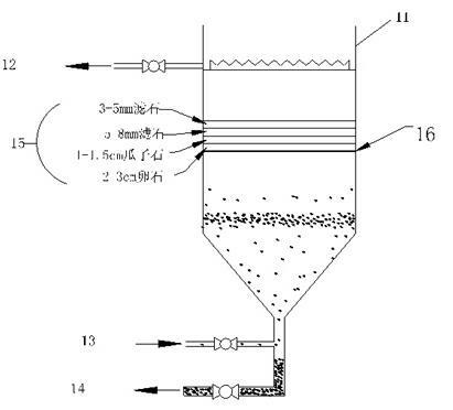
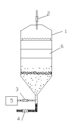
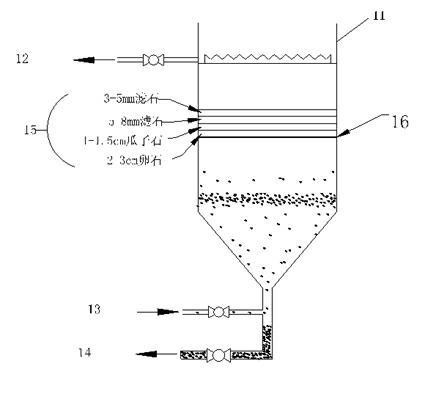
The invention relates to an automatic pressure flush type rapid filter which comprises a bucket, characterized in that a clear water discharge pipeline is arranged at the upper end of the bucket, a pre-filtering water pipeline and a sludge discharge pipeline are respectively arranged at the lower end of the bucket, a filtering material layer is arranged in the bucket and comprises a plurality of filtering material elementary layers arranged sequentially from the top down, and the filtering material elementary layers can be sequentially reduced in hole diameter from the bottom up according to particle diameters. In a flushing state, muddy water is filtered by layers from the bottom up through a water inlet pipeline and the filtering material layer, filtered clear water is discharged from the clear water discharge pipeline at the upper end, and sludge deposits in a sludge bucket and is discharged from the sludge discharge pipeline; and in a back flushing state, water reversely flows downwards from a clear water storage area to flush the filtering material layer by the self gravitational potential energy, and accumulated sludge is discharged from the sludge discharge pipeline below. The process is combined with a rapid filtration self-solidifying process, back washing is performed by the self pressure of the liquid level of the water, and a back washing pump is saved, thus saving the cost and having good effects.
Description
Self pressure flushing quick filter technical field The invention belongs to the field of water treatment, in particular to a self-pressure flushing type quick filter tank. Background technique Rapid filter (rapid filter), especially the traditional rapid filter, the filter material is generally single-layer fine sand graded filter material or coal, sand double-layer filter material, flushing with single water flushing, flushing water from the water tower (box) or Water pump supply. Ordinary fast filter is mainly composed of the following parts: (1) The filter body, which mainly includes water inlet pipes, drain tanks, filter media (filter material layer), filter medium support layer (cushion material layer) and distribution (drainage) water system. (2) Pipe gallery, which is mainly equipped with five kinds of pipes (canals), namely muddy water inlet pipe, clean water outlet pipe, flushing water inlet pipe, flushing drain pipe and primary filtration drain pipe, as w...
Claims
Login to View More Application Information
Patent Timeline
 IPC IPC(8): B01D24/16
Inventor 萧铭辰
Owner SHANGHAI ZHANGHUA FILM PURIFICATION
Features
- R&D
- Intellectual Property
- Life Sciences
- Materials
- Tech Scout
- Unparalleled Data Quality
- Higher Quality Content
- 60% Fewer Hallucinations
Learn More Browse by: Latest US Patents, China's latest patents, Technical Efficacy Thesaurus, Application Domain, Technology Topic, Popular Technical Reports.
© 2025 PatSnap. All rights reserved.Legal|Privacy policy|Modern Slavery Act Transparency Statement|Sitemap|About US| Contact US: help@patsnap.com


