

Hydraulic system used for revolving jogging control on crawler crane
A technology of crawler crane and hydraulic system, applied in the field of hydraulic system, can solve the problems of unavailability, high slewing speed, potential safety hazards, etc., and achieve the effects of convenient operation, simple structure, guaranteeing safety and high efficiency
Inactive Publication Date: 2011-06-15
SHANGHAI SANY TECH
View PDF5 Cites 5 Cited by
- Summary
- Abstract
- Description
- Claims
- Application Information
AI Technical Summary
Problems solved by technology
If the rotary handle has high sensitivity, the operator cannot perform low-speed rotary control under heavy load, which will cause certain safety hazards; When the slewing handle is set to the limit position, a high slewing speed cannot be obtained, which affects the working efficiency of the crawler crane
Method used
View moreImage
Smart ImageViewing Examples


Examples
Embodiment Construction
Login to View More PUM
 Abstract
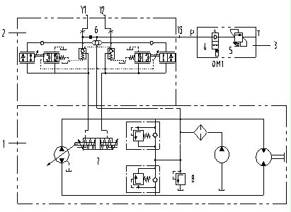
The invention provides a hydraulic system used for revolving jogging control on a crawler crane. The hydraulic system comprises a revolving pump motor loop, a revolving pump variable mechanism and a revolving slow valve, wherein the revolving slow valve comprises an electromagnetic directional valve and a pressure setting valve which are connected in series, one end of the revolving slow valve is connected with the input port of the revolving pump variable mechanism, and the other end of the revolving slow valve is connected with an oil tank. In the hydraulic system used for revolving jogging control on the crawler crane in the invention, a revolving slow valve is connected in parallel with the input port of the revolving pump variable mechanism to limit displacement of a revolving pump, thus revolving jogging control on the crawler crane can be effectively carried out, the structure is simple, the operation is simple, and the operation safety and high efficiency of the crawler crane can be effectively guaranteed.
Description
A Hydraulic System Used in Swing Micro-control of Crawler Crane technical field The invention relates to a hydraulic system, in particular to a hydraulic system for micro-motion control of the slewing of a crawler crane. Background technique All crawler cranes have a slewing function, that is, the upper car can rotate relative to the lower car. During the operation of the crawler crane, after lifting the heavy object on the vehicle and turning it at a certain angle, the heavy object is unloaded to the destination, and then rotated to complete a working cycle. Therefore, the slewing speed is an important indicator of crawler crane operation. Increasing the slewing speed can shorten the single operation time of the crawler crane and improve the operation efficiency. However, the higher the slewing speed of the crawler crane, the worse the safety and stability of its operation. Usually, the slewing speed of the crawler crane is realized by adjusting the angle of the slewi...
Claims
Login to View More Application Information
Patent Timeline
 Patent Type & AuthorityApplications(China)
IPC IPC(8): B66C23/86B66C23/36
Inventor陈元建
OwnerSHANGHAI SANY TECH