Screw type pneumatic drying machine and method
A technology of airflow drying and drying equipment, which is applied in the direction of dehydration/drying/concentrated sludge treatment, etc., can solve many problems, achieve the effects of reducing centrifugal force, prolonging the drying process, and improving sludge drying efficiency
Inactive Publication Date: 2011-06-15
SOUTHEAST UNIV
View PDF1 Cites 3 Cited by
- Summary
- Abstract
- Description
- Claims
- Application Information
AI Technical Summary
Problems solved by technology
At present, there are various types of drying devices, but due to the viscosity of sludge itself and its inherent characteristics, there are not many drying devices that can be directly applied to sludge drying
Method used
View moreImage
Smart ImageViewing Examples

Examples
Embodiment Construction
Login to View More PUM
 Abstract
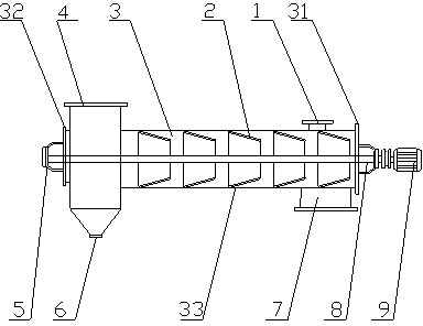
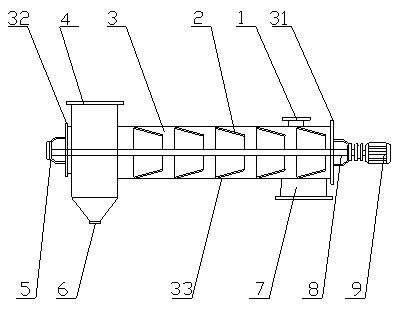
The invention relates to a screw type pneumatic drying machine and method. The screw type pneumatic drying machine comprises an airtight drying machine body (3), wherein the drying machine body (3) comprises a first end part (31), a second end part (32) and a shell (33); the first end part (31) and the second end part (32) are oppositely arranged, and the first end part (31); the first end part (31) and the second end part (32) are connected through the shell (33); and the second end part (32) and the shell (33) form an airtight working space. The drying machine also comprises a screw propulsion unit (2), a wet sludge feed port (1), high temperature smoke inlet (7) and a low temperature smoke outlet (4), wherein the screw propulsion unit (2) is installed in the working space; the wet sludge feed port (1) and the high temperature smoke inlet (7) are respectively arranged on the drying machine body (3); and the low temperature smoke outlet (4) is arranged on the drying machine body (3) and penetrates through the shell (33). The device and method are suitable for drying sludge, and have the advantages that the operation is continuous, the labor intensity is low, and the heat consumption is low.
Description
Spiral airflow drying device and method technical field The invention relates to a drying device and a drying method for sludge disposal. Background technique Sludge is the product of sewage treatment. Due to its high water content, complex composition, and more organic matter, it has a certain viscosity. At present, the disposal methods of sludge are mainly landfill and composting. Landfill disposal method will occupy a large amount of land resources and easily cause secondary pollution. According to the methods of sterilization and aging, compost has different fertilizer efficiency and safety. This disposal method can achieve the purpose of recycling, but the processing process is longer, and it will also occupy a large amount of land resources, and the disposal cost is also high; in addition, Sludge containing harmful components such as heavy metals should not be disposed of in this way. After drying, the sludge can be greatly reduced, harmless and resourceful. The ...
Claims
Login to View More Application Information
Patent Timeline
 Patent Type & Authority Applications(China)
IPC IPC(8): C02F11/12
Inventor 鲁维加郭宏伟
Owner SOUTHEAST UNIV
Features
- R&D
- Intellectual Property
- Life Sciences
- Materials
- Tech Scout
- Unparalleled Data Quality
- Higher Quality Content
- 60% Fewer Hallucinations
Learn More Browse by: Latest US Patents, China's latest patents, Technical Efficacy Thesaurus, Application Domain, Technology Topic, Popular Technical Reports.
© 2025 PatSnap. All rights reserved.Legal|Privacy policy|Modern Slavery Act Transparency Statement|Sitemap|About US| Contact US: help@patsnap.com