Chained oscillating tooth stepless speed change device

A technology of stepless variable speed and movable teeth, which is applied in transmission devices, belts/chains/gears, mechanical equipment, etc., can solve the problems of large normal pressing force, small transmission power, low mechanical efficiency, etc., and achieve transmission Improved power, torque, and mechanical efficiency, extended service life, and compact structure

Inactive Publication Date: 2011-06-15
郭质刚
View PDF0 Cites 3 Cited by
  • Summary
  • Abstract
  • Description
  • Claims
  • Application Information

AI Technical Summary

Problems solved by technology

[0002] Mechanical continuously variable transmission is a mechanical transmission device with continuously adjustable transmission ratio. It is widely used in various mechanical equipment because it can adapt to the requirements of changing working conditions or continuous changing speed during the operation of the machine, especially in recent years. For automotive transmissions, because the mechanical continuously variable transmission adopts friction transmission in the whole process of shifting, it requires a large normal pressing force, and has defects such as low mechanical efficiency, small transmission power, and small transmission torque.
[0003] Gear transmission has the advantages of large transmission power, large transmission torque, and high mechanical efficiency, but the transmission ratio is fixed, so it cannot meet the requirements of continuously variable speed

Method used


Image

  • Chained oscillating tooth stepless speed change device
  • Chained oscillating tooth stepless speed change device
  • Chained oscillating tooth stepless speed change device

Examples


Embodiment Construction

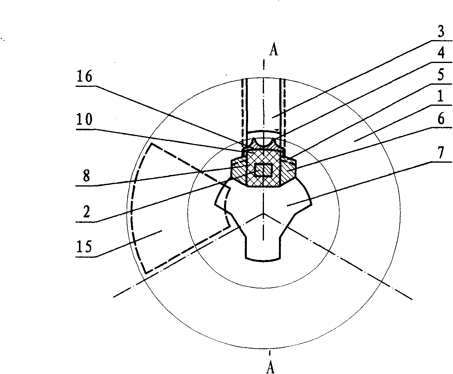
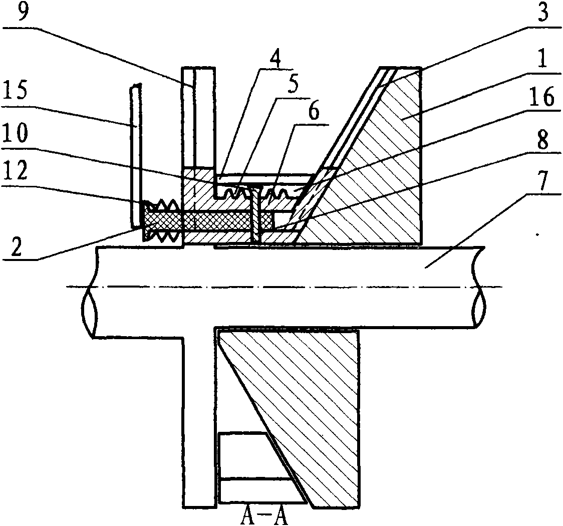
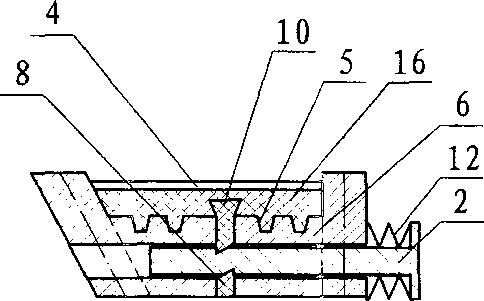
[0021] The driving shaft and the driven shaft are equipped with a flat plate fixed on the shaft and a cone plate that can slide on the shaft. There are 3 sets of radial dovetail grooves equally divided on the plate and the cone plate. The first type of movable gear seat is used. The equally divided movable tooth seat is clamped between the flat disk and the cone disk, and the chain guide plate is used to make the wrapping angle of the metal chain greater than or equal to 180 degrees. There are arc teeth on the inner side of the metal chain, which mesh with the two teeth on the movable tooth body , the cone on the passive shaft is pressed by a disc spring, and the cone on the driving shaft uses the rotation between the screw and the nut to compress or separate the moving cone. In a free state, the ejector rod is tensioned by a disc spring, so that The movable tooth body and the movable tooth seat are tightly combined by friction on the wedge groove surface. When changing speed, ...


PUM


Abstract

The invention discloses a chained oscillating tooth stepless speed change device. The chained oscillating tooth stepless speed change device comprises a metal chain, a driving shaft and a driven shaft; a fixed conical disk and a corresponding movable conical disk are arranged on the driving shaft and the driven shaft respectively; three groups of equant dovetail grooves which are perpendicular to a rotation direction are formed on the conical disks respectively; the dovetail grooves on the fixed conical disk correspond to those of the movable conical disk; dovetail blocks on oscillating tooth seats are embedded into the corresponding dovetail grooves on the conical disks; the wedge grove surfaces of each of oscillating tooth bodies and each of the oscillating tooth seats are rubbed and combined through an elastomer and by using an ejector rod and a compression plate so as to finish constant-speed transmission; and when the fixed conical disk and the movable conical disk approach and separate, three groups of equant oscillating tooth seats radially move at equal radii, the working radii of the oscillating tooth seats are changed, simultaneously the elastomer is compressed by a speed regulation plate to separate the oscillating tooth bodies and the oscillating tooth seats, and the oscillating tooth bodies freely move to be meshed with a chain randomly, so that the aim of changing the speed is fulfilled, friction transmission is guaranteed when speed is changed, gear transmission is guaranteed when speed is constant, and transmission power, torque and mechanical efficiency are greatly improved.

Description

technical field [0001] The invention relates to a mechanical speed change device, in particular to a chain-type movable tooth stepless speed change device. Background technique [0002] Mechanical continuously variable transmission is a mechanical transmission device with continuously adjustable transmission ratio. It is widely used in various mechanical equipment because it can adapt to the requirements of changing working conditions or continuous changing speed during the operation of the machine, especially in recent years. For automotive transmissions, because the mechanical continuously variable transmission adopts friction transmission in the whole process of shifting, it requires a large normal pressing force, which has defects such as low mechanical efficiency, small transmission power, and small transmission torque. [0003] Gear transmission has the advantages of large transmission power, large transmission torque, high mechanical efficiency, etc., but the transmis...

Claims


Application Information

Patent Timeline
Patent Type & Authority Applications(China)
IPC IPC(8): F16H37/02
Inventor 郭质刚
Owner 郭质刚
Why Eureka
Try Eureka