Intelligent concrete vibrating and plastering integrated equipment based on vibration wave signal control

A signal control and concrete technology, applied in roads, buildings, laying tracks, etc., can solve problems such as slow construction progress, extensive management, interference, etc., and achieve the effects of large power transmission dissipation, increased transmission power, and reduced transmission dissipation

Pending Publication Date: 2022-06-03
RAILWAY ENG RES INST CHINA ACADEMY OF RAILWAY SCI +1
View PDF6 Cites 1 Cited by
  • Summary
  • Abstract
  • Description
  • Claims
  • Application Information

AI Technical Summary

Problems solved by technology

However, in the actual construction process, due to the large interference of human factors and extensive management, it is difficult to accurately control the concrete vibration work by relying on supervisors and construction personnel to manually control the vibration, resulting in leakage, under-vibration, and vibration during construction. Over-vibration and other problems, the construction quality cannot be guaranteed, and the construction efficiency is difficult to improve
[0003] Concrete vibrated compactness can be evaluated by parameters such as density, strength, and pore structure after hardening, but an evaluation method similar to "post-feedback" is very unfavorable for actual engineering quality control. remedial measures to resolve
In the actual pouring process, there is no uniformly determined index for evaluating the compactness of concrete vibrating. The quality control of vibrating construction depends on human experience, which can only be roughly estimated and cannot be finely controlled.
Measuring and comparing the performance parameters of the fresh mix before and after vibration can evaluate the concrete compactness in real time, but the equipment structure is often complicated and the operation is difficult, so it is not suitable for on-site construction
[0004] The research on vibrating automation and intelligent construction is gradually increasing. The patent "An Automatic Vibrating Equipment" uses automatic vibrating equipment to replace manual work, which greatly reduces the labor burden of workers, realizes human-computer interaction, and improves vibrating efficiency. However, it is difficult to disassemble and move the equipment, so it is not suitable for long-term cast-in-place structures
The patent "A CRTSⅢ Ballastless Track Base Plate Concrete Automatic Forming Machine" can accurately plaster and lift the CRTS Ⅲ ballastless track base plate, but it does not have the vibration function, and the structure is complicated, so it can only be used in specific structures
"A Smart Vibrator for Cast-in-place Ballastless Track of High-speed Railway" realizes on-site pouring and automatic vibration of high-speed rail track slabs by pre-setting the vibration time, insertion depth and vibration interval, but it cannot intelligently judge the degree of concrete density in real time
In addition, for example, GPS devices are used to test parameters such as the position, depth, and angle of the vibrating rod, and image simulation analysis software and devices are used to monitor the vibrating construction. New technologies have begun to be applied in vibrating construction. These studies can intelligently determine Construction status and planned construction route, but construction still relies heavily on manpower, it is impossible to determine the compactness of concrete vibration in real time, and it is impossible to realize precise and unmanned intelligent vibration construction of concrete
After vibrating, it is necessary to carry out a second finishing process on the surface. At present, the surface plastering construction relies heavily on manpower, the construction progress is slow, and the process connection time is long

Method used


Image

  • Intelligent concrete vibrating and plastering integrated equipment based on vibration wave signal control
  • Intelligent concrete vibrating and plastering integrated equipment based on vibration wave signal control
  • Intelligent concrete vibrating and plastering integrated equipment based on vibration wave signal control

Examples


Embodiment Construction

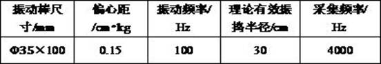
[0021] The technical solutions of the present invention will be further described in detail below through embodiments and in conjunction with the accompanying drawings. Take the construction of CRTSIII type ballastless track base plate as an example to explain in detail. CRTSIII type ballastless track base plate is 2900mm wide and 190mm high, with steel mesh inside. The key parameters of the selected machine are shown in Table 1, and the concrete mix ratio and its working performance are shown in Table 2.

[0022] Table 1 Parameters of the integrated machine for intelligent vibrating and plastering

Table 2 Concrete mix ratio and its working performance

A concrete intelligent vibrating and plastering surface integrated equipment based on vibration wave signal control, and its working steps:

(1) According to the structural width a=2900mm, 5 groups of intelligent vibrating and plastering integrated machines (hereinafter referred to as machines) are placed on the pour...


PUM


Abstract

The invention relates to intelligent concrete vibrating and plastering integrated equipment based on vibration wave signal control. The intelligent concrete vibrating and plastering integrated equipment is mainly composed of an advancing system, a vibrating working system, a plastering working system, a data processing center and other modules. The vibrating working system and the plastering working system can realize fine construction of vibrating and plastering under the control of the data processing center; the data processing center processes the collected vibration wave signals and judges the concrete vibration compaction degree according to the change rule of the vibration wave signals; the advancing system can achieve accurate adjustment of displacement and construction positions, and intelligent construction of a long-line structure is achieved. According to the invention, automatic and accurate construction in the whole process of concrete vibrating and plastering is realized, the device is suitable for plane structure concrete projects such as long-line continuous cast-in-place high-speed railway base plates, ballastless track beds, highway pavements and airport runways, and the concrete construction quality and the construction efficiency are improved.

Description

technical field [0001] The invention belongs to the field of concrete construction, and in particular relates to an integrated equipment for intelligent vibrating and plastering of concrete based on vibration wave signal control, which is suitable for efficient and accurate construction of continuous long-line cast-in-place planar structures such as ballastless track concrete bases and ballast beds. Background technique [0002] Vibration is an important link in the concrete construction process. Through low-amplitude and high-frequency vibration, energy is transferred to the concrete mixture, so that all particles within the vibration range are forced to vibrate. Vibration reduces the viscosity and internal friction of the concrete mixture within the effective range of the vibration, changes the fluidity of the slurry, the aggregate particles sink and slide under the action of gravity, and the large air bubbles float up and discharge under the action of buoyancy. Or be vibr...

Claims


Application Information

Patent Timeline
Patent Type & Authority Applications(China)
IPC IPC(8): E01B29/00
CPCE01B29/00E01B29/005
Inventor 李化建温家馨李子春黄法礼易忠来王振袁政成谢永江靳昊程欢
Owner RAILWAY ENG RES INST CHINA ACADEMY OF RAILWAY SCI
Why Eureka
Try Eureka