Multi-disk high-power moment-limiting permanent magnet eddy current coupling

A permanent magnet eddy current, high-power technology, applied in electromechanical transmission devices, electromechanical devices, electrical components, etc., can solve the problems of incomplete unloading, inability to use high-power transmission systems, scrapping of couplings, etc., to prevent collisions and wear , Improve the transmission power and reduce the impact

Active Publication Date: 2018-11-20
TAIYUAN INST OF CHINA COAL TECH & ENG GROUP +1
View PDF9 Cites 0 Cited by
  • Summary
  • Abstract
  • Description
  • Claims
  • Application Information

AI Technical Summary

Problems solved by technology

However, there are still some problems in the disc-type moment-limiting permanent magnet eddy current coupling widely used in the field of mechanical transmission: (1) When the permanent magnet coupling is working, due to the axial clearance of the motor or reducer bearing, the shaft Axial series movement cannot guarantee the gap between the conductor disk and the magnet disk; when the bearing is damaged, the axial movement of the shaft will cause the magnet disk and the conductor disk to collide with each other, causing damage
(2) To increase the transmission power, one method is to increase the diameter of the magnet disk and the conductor disk, but this method will limit its application in mechanical transmission occasions with limited radial space; another method is to increase the magnet The number of disks and conductor disks, and multiple magnet disks and multiple conductor disks are cascaded, but in this method, the conductor disks and magnet disks are respectively fixed on the motor shaft and the reducer shaft, which will cause damage due to the motor shaft or deceleration. The movement of the shaft causes the contact and collision between the conductor disk and the magnet disk or the gap between the two sides of the conductor disk is not equal, and additional axial force acts on the bearing of the motor or reducer
If it is applied to occasions with large load power and large impact load, it has serious shortcomings:
[0009] ①The gap between the magnet disk and the conductor disk cannot be guaranteed, and it is easy to collide
When the permanent magnet coupling is assembled with the motor and the reducer, it is difficult to ensure that the air gaps on both sides of the conductor disc are equal, so that the axial repulsion on both sides of the conductor disc is not equal during operation, thereby generating additional axial force on the motor and reducer bearings. When the axial movement of the motor shaft and the reducer shaft is too large, it is easy to make the conductor disk and the magnet disk contact, resulting in frictional damage when the two are running; especially when the motor and reducer bearings are damaged, the motor shaft or reducer shaft The movement will directly lead to contact and friction damage between the conductor disk and the magnet disk, and the entire coupling will be scrapped
[0010] ②The gap between the permanent magnet disk and the conductor disk cannot be adjusted. When a large impact load is encountered, the slip between the permanent magnet disk and the conductor disk increases. Although the transmission torque is reduced, it cannot be completely unloaded. This situation continues to occur , the permanent magnet coupling will generate serious heat, and only relying on a small amount of cooling fins on the motor side and the load side to dissipate heat (the greater the power, the more serious the heating, but the cooling fins are not increased), the heating problem is far from being solved, so It will cause the temperature of the permanent magnet to rise until it is demagnetized, and finally the permanent magnet coupling is scrapped
[0011] ③This patent has no stationary components, cannot be equipped with a cooling system, and does not provide strategies and methods for solving heat problems during high-power transmission, so it cannot be used in high-power transmission systems
[0020] This innovative coupling belongs to the radial flux permanent magnet eddy current coupling, which is not suitable for occasions where the radial size is limited

Method used


Image

  • Multi-disk high-power moment-limiting permanent magnet eddy current coupling
  • Multi-disk high-power moment-limiting permanent magnet eddy current coupling
  • Multi-disk high-power moment-limiting permanent magnet eddy current coupling

Examples


Embodiment Construction

[0046] In conjunction with accompanying drawing, the specific embodiment of the present invention is described further:

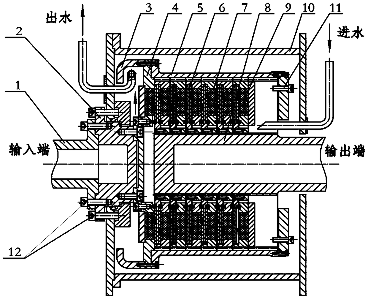
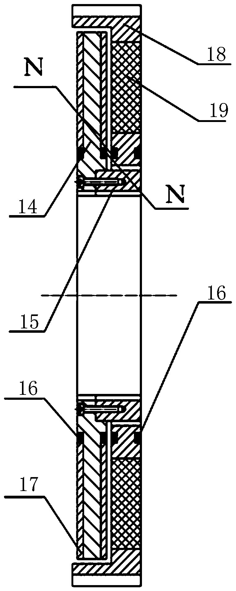
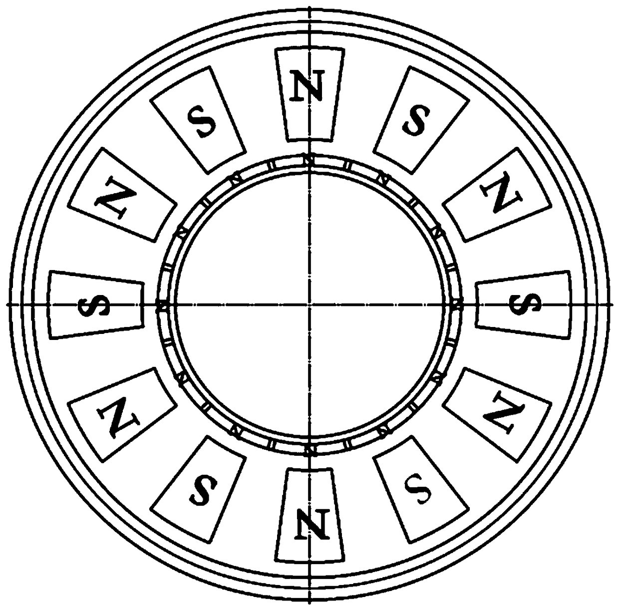
[0047] Such as figure 1 The multi-disk high-power moment-limiting permanent magnet eddy current coupling shown includes input shaft sleeve, transition connection disc, left auxiliary housing, spline sleeve, input side magnet disc, several middle magnet discs, and output side magnet disc , several conductor disks, output spline shafts, axial limit screws, supporting shells, etc., the multi-disc structure is an index of magnet disks and conductor disks stacked alternately to form a multi-disk structure, which can be adjusted according to power requirements Design the number of magnet disks and conductor disks, the active rotor composed of magnet disks, spline sleeves, left auxiliary shells, right end plates, etc. is connected to the motor shaft; the driven rotor composed of conductor disks, output spline shafts, etc. Reducer input shaft connection. Except f...


PUM


Abstract

The invention belongs to the field of mechanical transmission. In order to use the shaft coupling to limit a transmission torque of a motor and a transmission system, to protect transmission components from shock overload and to ensure the normal operation of a host machine, a multi-disc type large power limited-moment type permanent-magnetism eddy current shaft coupling is thus provided. The multi-disc type large power limited-moment type permanent-magnetism eddy current shaft coupling comprises an input shaft sleeve, a transition connection disc, a left auxiliary casing, a spline sleeve, an output spline shaft, etc. Several magnet plates and conductor plates which are alternately stacked are arranged in the spline sleeve. Each of the magnet discs is circumferentially embedded with an even-number of permanent magnets in which N and S poles are alternately arranged. Permanent magnets of the adjacent magnet discs are axially opposed, and magnetic poles of the adjacent magnet discs are opposite. Inner rings of the two adjacent surfaces of each two adjacent conductor disc and magnet disc are provided with a plurality of small magnets axially opposed and having the same magnetic poles, so that the magnet plate and the conductor plate are not in contact due to the repulsive force. The multi-disc type large power limited-moment type permanent-magnetism eddy current shaft coupling of the invention employs a multi-disc type structure, so that the permanent-magnetic driving power can be raised without increase in the radial structural dimension of a permanent magnetism transmission device. The multi-disc type large power limited-moment type permanent-magnetism eddy current shaft coupling can be widely applied to occasions where the radial space is limited and the axial direction space is large.

Description

technical field [0001] The invention belongs to the field of mechanical transmission and is mainly applied to mining scraper conveyors and crushers and other equipment with frequent impacts, in particular to a multi-disk high-power moment-limiting permanent magnet eddy current coupling. Background technique [0002] The transmission mode of motor-coupling-reducer is the most commonly used driving mode in mechanical equipment. In this transmission structure, the input end of the coupling is connected to the output shaft of the motor through a shaft sleeve with a keyway, and the output end is connected to the input shaft of the reducer. During the operation of the transmission system, due to the motion inertia of the motor rotor, when there is an impact load, it will form an inertial impact on the transmission components in the transmission system, damage the transmission components, and affect the reliable operation of the transmission system. Fault shutdowns occur from time ...

Claims


Application Information

Patent Timeline
Patent Type & Authority Patents(China)
IPC IPC(8): H02K51/00
CPCH02K51/00
Inventor 张彦禄王腾樊运平李建国张庚云王赟李彬彬成志峰桑盛远于建华张春英石涛
Owner TAIYUAN INST OF CHINA COAL TECH & ENG GROUP
Why Eureka
Try Eureka