Self-monitoring system of valve-based electronic device of converter valve

A valve-based electronic equipment and self-monitoring technology, applied in the direction of measuring electricity, measuring devices, measuring electrical variables, etc., can solve the problems of incomplete self-recovery function of the board, unable to locate the faulty board, etc., and achieve the reduction of complete failure to work. , the effect of reducing the likelihood

Active Publication Date: 2011-06-15
CHINA ELECTRIC POWER RES INST +1
View PDF4 Cites 4 Cited by
  • Summary
  • Abstract
  • Description
  • Claims
  • Application Information

AI Technical Summary

Problems solved by technology

[0003] In the DC projects currently in operation, although the valve-based electronic equipment has self-detection and reporting functions, it generally cannot achieve the function of locating the faulty board, and the self-recovery function in the board is not perfect

Method used


Image

  • Self-monitoring system of valve-based electronic device of converter valve
  • Self-monitoring system of valve-based electronic device of converter valve
  • Self-monitoring system of valve-based electronic device of converter valve

Examples


Embodiment Construction

[0022] The design method of the self-inspection system of the valve-based electronic equipment of the present invention is divided into two parts: the self-inspection within the board and the self-inspection between the boards.

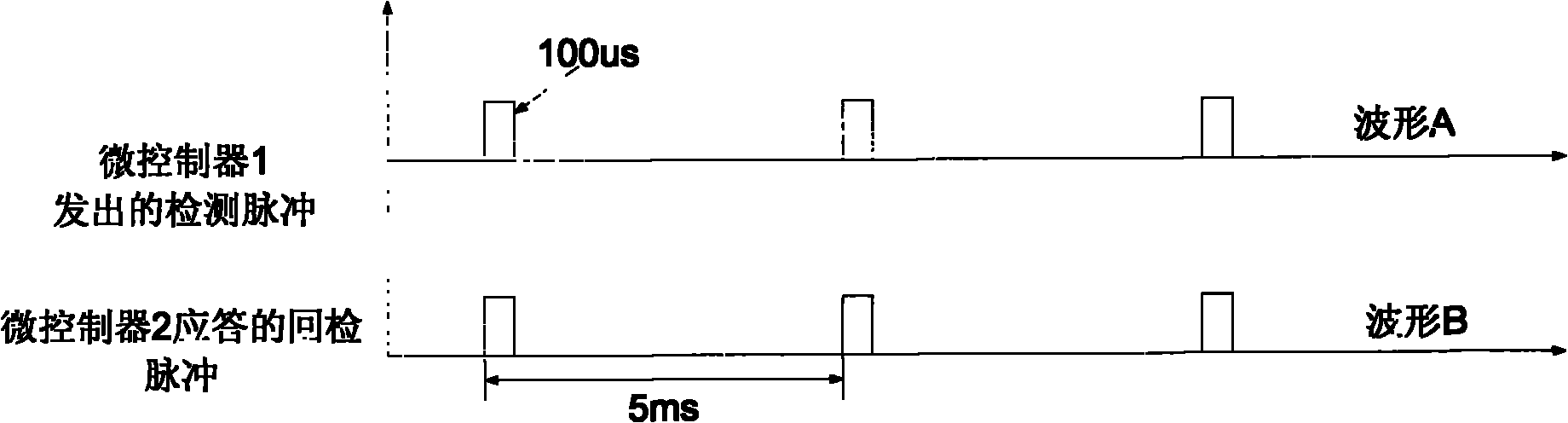
[0023] figure 1 It is a schematic diagram of the self-inspection pulse coding between the microcontroller 2 detected by the microcontroller 1 on the main control board in real time. Microcontroller 1 sends 100us pulses to microcontroller 2 every 5ms, and microcontroller 2 returns the received pulses to microcontroller 1 without delay. The program of microcontroller 2 returning pulses without delay is the main In a part of the program, if the microcontroller 1 receives the returned 100us pulse, it means that the microcontroller 2 is working normally, otherwise it sends a switching request command to the control and protection system. Microcontroller 2 detects the working status of microcontroller 1 in real time. If no detection pulse of 100us is recei...


PUM


Abstract

The invention relates to the field of high-voltage direct-current (HVDC) transmission, in particular to a self-monitoring system of a valve-based electronic device of a converter valve. According to the self-monitoring system provided by the invention, board card self-detection and mutual detection among board cards are respectively designed, and the two design methods are combined so that the operation state of the board cards and the positions of fault board cards can be accurately reported. Therefore, the operation reliability of various control board cards in the valve-based electronic device is increased, and a convenient man-machine display system is provided for operation staff.

Description

technical field [0001] The invention relates to the field of high-voltage direct current transmission (HVDC), in particular to a self-monitoring system for valve base electronic equipment of a converter valve. Background technique [0002] In high-voltage direct current transmission, the valve-based electronic equipment of the converter valve is the first-level monitoring equipment for the converter valve. According to the received control command of the extreme control system, the device directly realizes the triggering and blocking operations of the converter valve, and collects the reported information of each thyristor level in real time, and feeds it back to the extreme control system. Therefore, the normal operation of valve-based electronic equipment is very important to the operation of the entire system. This requires firstly that the necessary automatic reset can be performed when the valve-based electronic equipment occasionally runs abnormally; The position is ...

Claims


Application Information

Patent Timeline
Patent Type & Authority Applications(China)
IPC IPC(8): G01R31/00
Inventor 魏晓光郝长城王华锋
Owner CHINA ELECTRIC POWER RES INST
Why Eureka
Try Eureka