Mixed time sequence synchronous control method in physical simulation

A semi-physical simulation, timing synchronization technology, applied in the field of simulation, to achieve the effect of flexibility and scalability

Inactive Publication Date: 2011-06-15
CHANGCHUN INST OF OPTICS FINE MECHANICS & PHYSICS CHINESE ACAD OF SCI
View PDF4 Cites 12 Cited by
  • Summary
  • Abstract
  • Description
  • Claims
  • Application Information

AI Technical Summary

Problems solved by technology

[0004] In order to solve the working problem of data interaction and coordination between existing real-time physical simulation deduction and non-real-time simulation control, the present invention provides a hybrid timing synchronization control method in semi-physical simulation

Method used


Image

  • Mixed time sequence synchronous control method in physical simulation
  • Mixed time sequence synchronous control method in physical simulation
  • Mixed time sequence synchronous control method in physical simulation

Examples


specific Embodiment approach 1

[0016] Specific implementation mode 1. Combination Figure 1 to Figure 3 Describe this embodiment, the hybrid timing synchronization control method in hardware-in-the-loop simulation, this method is realized by the following steps:

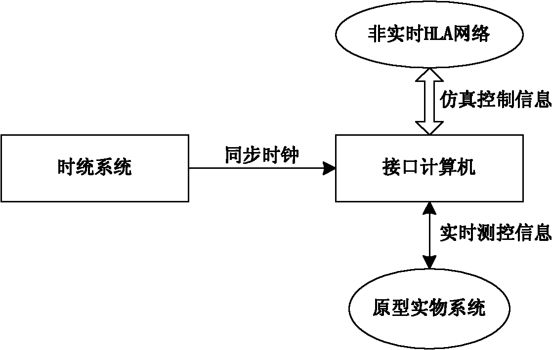
[0017] Step 1. The interface device starts the simulation process according to the simulation data received from the simulation control system, and realizes the physical interrupt response of the clock system through the serial interface interrupt mode;

[0018] Step 2, the interface device described in step 1 transmits the received simulation data to the prototype physical system, and the prototype physical system receives and obtains the simulation data;

[0019] Step 3, the interface device receives the status and data collected in real time by the prototype physical system; and transmits the status and data to the simulation control system;

[0020] Step 4: Calculate the simulation target data of the next cycle according to the data obtained ...

specific Embodiment approach 2

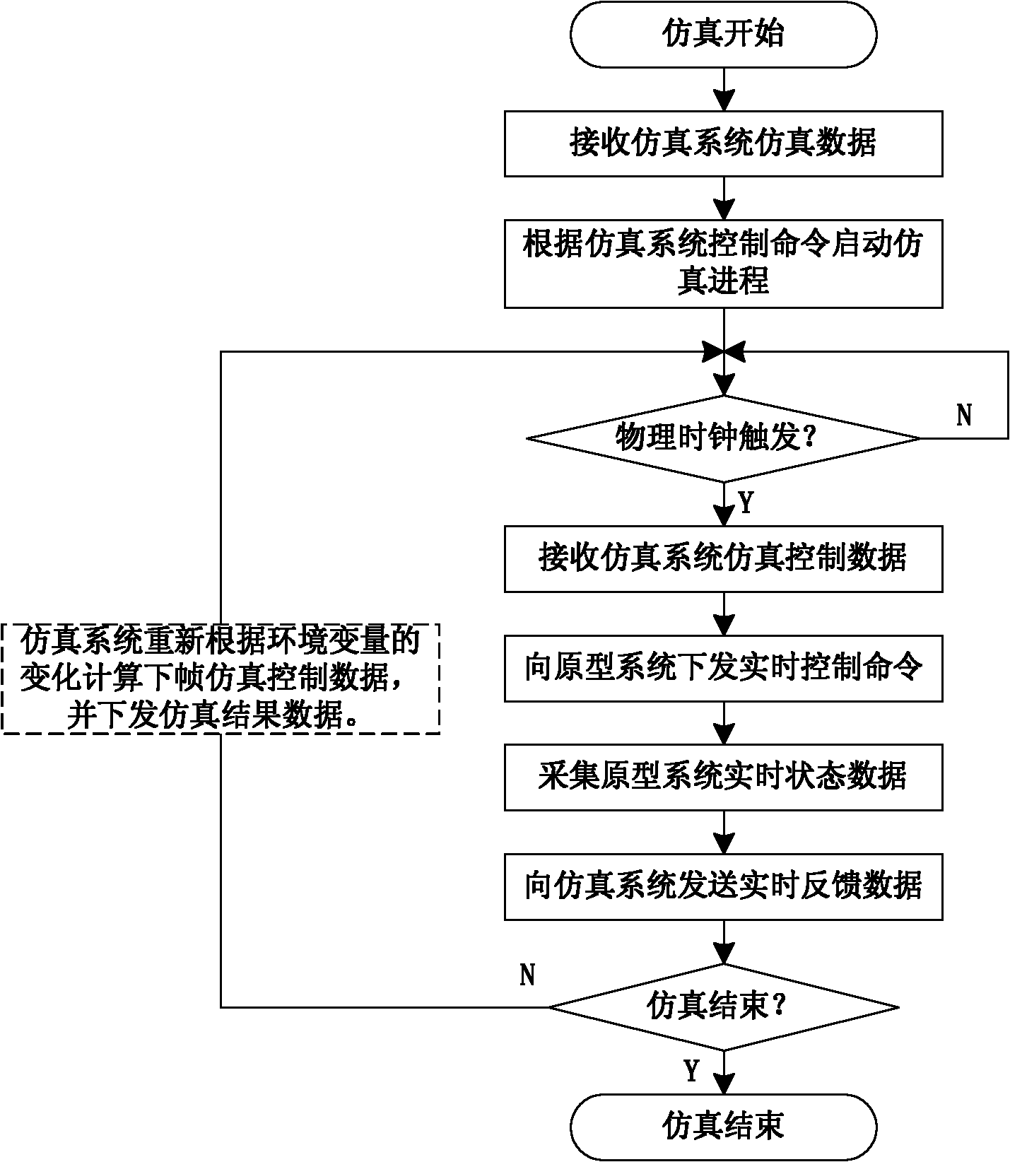
[0023] Specific embodiment two, combine Figure 4 Describe this embodiment mode, this embodiment mode is the specific simulation process of implementing the hybrid timing synchronization control method in the hardware-in-the-loop simulation described in 1:

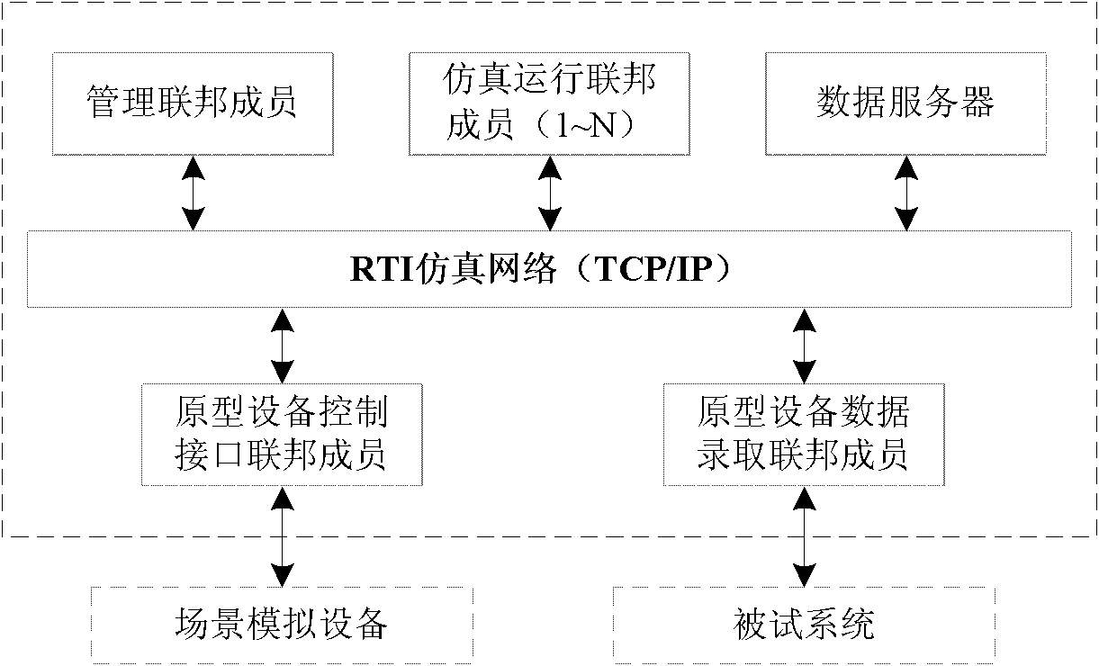
[0024] combine figure 2 and image 3 , using hybrid timing synchronous control (MSSC) technology to realize hardware-in-the-loop simulation control, image 3 Take the 100Hz control frequency as an example: the core of MSSC is to set two sets of timing sequences in the interface member, the simulation timing and the physical timing, trigger the internal simulation timing operation through the physical timing, and then trigger the simulation through the information interaction under the control of RTI in the interface simulation timing network operation. The information exchange process is as follows:

[0025] 1. The management member starts the simulation test according to the operation instruction, and sends the simul...


PUM


Abstract

The invention discloses a mixed time sequence synchronous control method in physical simulation, relating to the technical field of simulation control and solving the working difficulties of data interaction and coordination between the real-time physical simulation derivation and non-real-time simulation control in the prior art. The mixed time sequence synchronous control method comprises the following steps: utilizing the physical time sequence of a real-object system to reversely trigger a non-real-time simulation time sequence; and leading the system to realize time-sequence unification and data exchange on prototype interface equipment by establishing effective and synchronous management. Under the mixed time sequence synchronous control mechanism, a simulation system progressing according to self step size originally can be matched with the physical time sequence under a certain condition. As the mixed time sequence synchronous mechanism is applied in the physical simulation, the simulation system not only considers the requirement of the prototype system simulation for real-time property under the high-accuracy requirements, but also ensures that an effective support which is provided for network integration and data interaction by an advanced simulation system frame based on an HLA (high level architecture) is given full play, so that the flexibility and expandability of application of the physical simulation system are improved.

Description

technical field [0001] The invention relates to the field of simulation technology, in particular to a system synchronization control method under real-time and non-real-time mixed control sequence. Background technique [0002] The hardware-in-the-loop simulation test system, as an important means of complex system research and development, performance test and index detection, has been paid more and more attention. Semi-physical simulation test is a kind of test method that is directly participated by real objects and combined with the application of simulation environment. Its system structure includes the following parts: simulation control system, environment simulation equipment and equipment under test. [0003] Determined by the working nature of the hardware-in-the-loop simulation system, its architecture generally needs to include two parts, real-time and non-real-time, the real-time part is used to complete real-time control and data collection of the environmenta...

Claims


Application Information

Patent Timeline
IPC IPC(8): G05B17/02
Inventor 李岩杨词银路明李姜于洋王思雯于国权王建军崔爽
Owner CHANGCHUN INST OF OPTICS FINE MECHANICS & PHYSICS CHINESE ACAD OF SCI
Why Eureka
Try Eureka