Slide rheostat with dustproof structure

A technology of sliding rheostat and dust-proof structure, which is applied in the direction of sliding contact resistors, resistor shells/packaging shells/potting, etc., and can solve the problem of damage to circuits or electronic devices, failure of sliding button 4, and inability to change the resistance of the access circuit Size and other issues

Inactive Publication Date: 2011-06-15
NANJING LG PANDA APPLIANCES
View PDF4 Cites 5 Cited by
  • Summary
  • Abstract
  • Description
  • Claims
  • Application Information

AI Technical Summary

Problems solved by technology

[0007] Due to the existence of the slideway 5 in the sliding rheostat 1 of the prior art, dust will fall into the sliding rheostat 1 through the slideway 5, causing the sliding button 4 to fail, that is, the resistance of the access circuit cannot be changed by sliding the sliding button

Method used


Image

  • Slide rheostat with dustproof structure
  • Slide rheostat with dustproof structure
  • Slide rheostat with dustproof structure

Examples


Embodiment Construction

[0025] The present invention will be described in detail below in conjunction with the accompanying drawings and embodiments. In the drawings, the same symbols are used for the same components as those of the prior art.

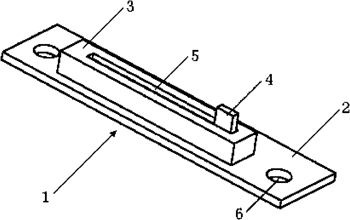
[0026] figure 2 It is a structural schematic diagram of a sliding rheostat in the prior art. The shown sliding rheostat 1 includes a printed circuit board 2 arranged at the bottom and a rheostat 3 welded on the top of the printed circuit board 2 , and two ends of the printed circuit board are respectively provided with mounting holes 6 for fixing the sliding rheostat 1 . The middle of the rheostat 3 is provided with a through slideway 5 along the axial direction, and a slide button 4 is arranged in the slideway 5, and the resistance of the connected circuit part is changed by the slide button 4 sliding along the slideway in the slideway 5.

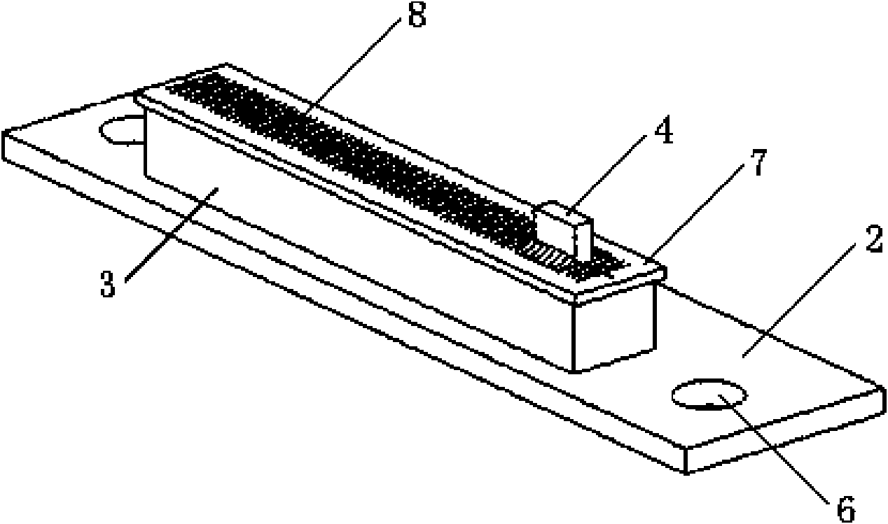
[0027] image 3 It is a structural perspective view of a sliding rheostat with a dust-proof structure of the presen...


PUM


Abstract

The invention discloses a slide rheostat with a dustproof structure. The slide rheostat comprises a printed circuit board and a rheostat welded on the printed circuit board; a through chute is formed in the middle of the rheostat; a slide button is arranged in the chute; a dustproof gasket is connected on the chute of the rheostat; a thin strip structure is formed at a position, corresponding to the chute, of the dustproof cushion; the thin strip structure of the dustproof cushion consists of a longitudinal incision formed at the centre line of the dustproof cushion along the direction of the chute, and a plurality of equally spaced transverse incisions, which are arranged on both sides of the longitudinal incision and vertical to the longitudinal incision; and the transverse incisions form a plurality of structures which are compactly contacted with one another and separable from one another. When the slide button of the dustproof cushion designed in the slide rheostat slides, the thin strip structure at the position where the slide button reaches is turned up to make the slide button pass through, while other parts are closed, so dusts can be effectively prevented from falling into the slide rheostat through the chute and further making the slide button be out of order; meanwhile, static electricity can be prevented from passing through the chute and directly contacting the printed circuit board to damage circuits or electronic devices on the printed circuit board.

Description

technical field [0001] The invention relates to a sliding rheostat, in particular to a sliding rheostat with a dust-proof structure. Background technique [0002] Sliding rheostat is one of the commonly used devices in electricity. It is widely used in household appliances such as vacuum cleaners and air conditioners, as well as communication tools, automobiles, instrumentation and other fields. A sliding rheostat is an electrical component that can be adjusted to obtain different resistances. By changing the resistance of the connected circuit part, the current in the circuit is changed, thereby changing the voltage across the conductor (electrical appliance) connected in series. It can be used as a current limiter or a voltage divider in the circuit to protect the circuit. [0003] figure 1 It is a structural diagram of the position of the sliding rheostat applied in the vacuum cleaner. The sliding rheostat 1 shown in the figure is installed in the top cover 11 of the va...

Claims


Application Information

Patent Timeline
IPC IPC(8): H01C10/38H01C1/02
Inventor 杨帆
Owner NANJING LG PANDA APPLIANCES
Why Eureka
Try Eureka