Protection circuit of storage capacitor

An energy storage capacitor and protection circuit technology, applied in emergency protection circuit devices, emergency protection circuit devices for limiting overcurrent/overvoltage, circuit devices, etc., can solve problems such as capacitor discharge, large current, explosion, etc.

Inactive Publication Date: 2011-06-15
上海申瑞电力科技股份有限公司
View PDF5 Cites 5 Cited by
  • Summary
  • Abstract
  • Description
  • Claims
  • Application Information

AI Technical Summary

Problems solved by technology

[0002]At present, in the power distribution network operating mechanism, the operating power supply is generally DC, because the moment the operating mechanism operates requires a lot of energy (several amperes or even tens of amperes ), large-capacity energy storage capacitors are often used to store the required energy. The traditional implementation method is to charge the capacitor directly after rectifying the alternating current. Since the necessary protection circuit is not added, when the capacitor is charged, the current is very large, which is easy to cause The circuit breaker accidentally trips; when the operating mechanism is stuck or even short-circuited, it is easy to burn out the rectifier circuit; and when the voltage rises abnormally beyond the rated voltage of the capacitor, there may be vicious accidents such as capacitor discharge or even explosion

Method used


Image

  • Protection circuit of storage capacitor
  • Protection circuit of storage capacitor

Examples


Embodiment Construction

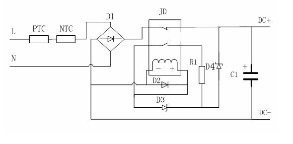
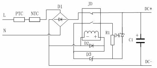
[0013] Such as figure 1 Shown circuit diagram of the present invention, wherein L, N are AC input terminals, DC+, DC- are DC power supply output terminals, positive temperature coefficient thermistor PTC, negative temperature coefficient thermistor NTC, rectifier bridge circuit D1, relay JD, use The diode D2 used for relay reverse voltage release, the first voltage stabilizing diode D3, the second voltage stabilizing diode D4, the current limiting resistor R1, and the energy storage capacitor C1.

[0014] Its working process is as follows:

[0015] When the power supply is powered on, due to the characteristics of the negative temperature coefficient thermistor NTC, it has a certain resistance value at low temperature, thereby limiting the power-on surge current, while in normal operation, due to self-heating, the resistance value decreases, It will not affect the system. Selecting a suitable negative temperature coefficient thermistor NTC according to the needs can limit th...


PUM


Abstract

The invention provides a protection circuit of a storage capacitor, and relates to the electricity field. The protection circuit is used for solving the protection problem of a high-capacity storage capacitor, and comprises a rectifying circuit and the storage capacitor, wherein the rectifying circuit is connected with an alternating current (AC) input end; the storage capacitor is connected with an direct current (DC) output end; an overvoltage protection circuit for the storage capacitor is connected between the rectifying circuit and the storage capacitor in parallel and comprises a relay with a normally open contact and a normally closed contact, a first voltage-regulator diode, a second voltage-regulator diode and a current-limiting resistor; the normally closed contact of the relay is connected between the output of the rectifying circuit and the positive pole of the storage capacitor in series; the normally open contact of the relay is connected with a circuit in series, and the circuit comprises the current-limiting resistor and the second voltage-regulator diode; the first voltage-regulator diode is connected with a circuit in parallel, and the circuit comprises the current-limiting resistor and the normally open contact of the relay; the positive pole of the second voltage-regulator diode is connected with the current-limiting resistor and the negative pole of the first voltage-regulator diode; and the negative pole is connected with the positive pole of the storage capacitor. The protection circuit can realize the overvoltage protection for the storage capacitor.

Description

technical field [0001] The present invention relates to an energy storage capacitor, and further relates to a protection circuit for the energy storage capacitor. Background technique [0002] At present, in the operating mechanism of the power distribution network, the operating power is generally DC. Since the moment of operation of the operating mechanism requires a lot of energy (several amperes or even tens of amperes), large-capacity energy storage capacitors are often used to store the required energy. , the traditional implementation method is to charge the capacitor directly after rectifying the AC power. Since no necessary protection circuit is added, when the capacitor is charged, the current is very large, which may easily cause the circuit breaker to trip by mistake; when the operating mechanism is stuck or even short-circuited, It is easy to burn out the rectifier circuit; and when the voltage rises abnormally and exceeds the rated voltage of the capacitor, the...

Claims


Application Information

Patent Timeline
Patent Type & Authority Applications(China)
IPC IPC(8): H02H7/16H02H9/02H02H9/04
Inventor 王成修
Owner 上海申瑞电力科技股份有限公司
Why Eureka
Try Eureka