Positively arranged tire for bottom frame of railway vehicle

A railway vehicle and underframe technology is applied in the field of railway vehicle underframe tooling, which can solve the problems affecting the assembly efficiency of steel structure underframe components, the inconsistency of design benchmarks and process benchmarks, affecting the installation accuracy of bolsters and other components, and achieves positioning. Reasonable way, high positioning accuracy and high production efficiency

Active Publication Date: 2011-06-22
CRRC NANJING PUZHEN CO LTD
View PDF14 Cites 23 Cited by
  • Summary
  • Abstract
  • Description
  • Claims
  • Application Information

AI Technical Summary

Problems solved by technology

[0004] It can be seen that with the development of technology, this assembly method can no longer adapt to the development of technology, which affects the assembly efficiency of steel structure chassis components. At the same time, reverse assembly makes the design benchmark and process benchmark inconsistent, which affects the installation of parts such as corbel beams. Accuracy, due to more processes, greatly reduces production efficiency

Method used


Image

  • Positively arranged tire for bottom frame of railway vehicle
  • Positively arranged tire for bottom frame of railway vehicle
  • Positively arranged tire for bottom frame of railway vehicle

Examples


Embodiment Construction

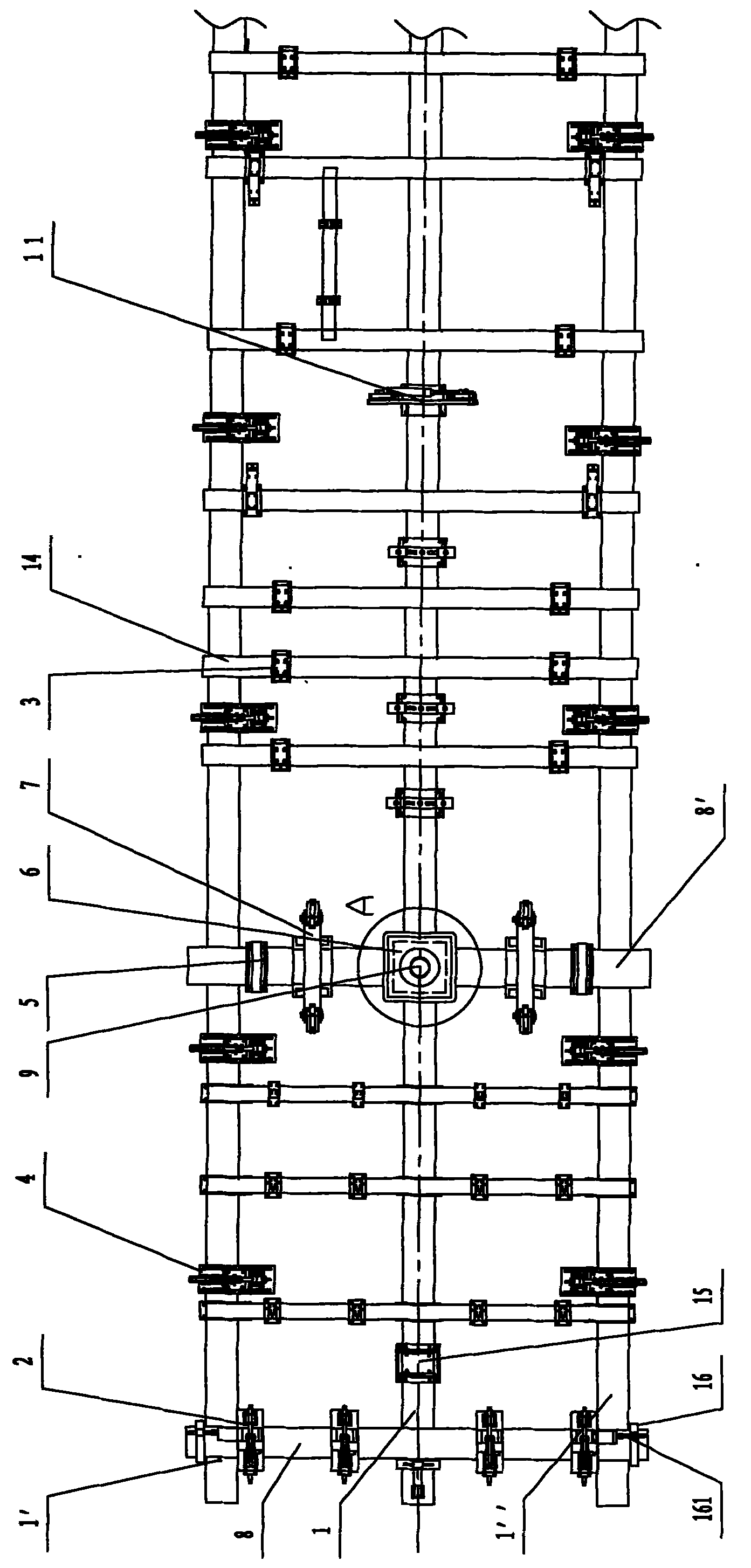
[0029] Such as figure 1 As shown, it is a schematic diagram of the structure of the underframe of the railway vehicle in this embodiment. In the figure, only the structure of the half side of the tire is shown, and the other half is symmetrical to the structure. The tire includes three longitudinal frames 1, 1 ', 1", four large horizontal frames 8, 8', the upper end surfaces of the vertical frames 1, 1', 1" are located in the same horizontal plane (the flatness is about 1mm), the large horizontal frames 8, 8' and the vertical frames 1, 1 ', 1" are vertical and can be moved and positioned arbitrarily on the vertical frames 1, 1', 1", and the two large horizontal frames 8 are located at the outer ends of the vertical frames 1, 1', 1", corresponding to the end beams of the bottom frame. The two large horizontal frames 8' are located at the inner ends of the vertical frames 1, 1', 1", corresponding to the corbel beams on both sides of the underframe, and the large horizontal frame...


PUM


Abstract

The invention discloses a positively arranged tire for a bottom frame of a railway vehicle. The positively arranged tire comprises three longitudinal frames which are parallel to one another, and four large cross frames; two large cross frames are positioned at the outer ends of the longitudinal frames and correspond to the end beam of the bottom frame, and the other two large cross frames are positioned at the inner ends of the longitudinal frames and correspond to sleeper beams on two sides of the bottom frame; the large cross frames at the outer ends are provided with end beam positioning and clamping devices respectively; the longitudinal frames on the outer sides are provided with side beam positioning and clamping devices respectively; the upper end surfaces of the middle parts of the large cross frames at the inner ends are provided with upper center plate positioning surfaces respectively; each of the upper center plate positioning surfaces is provided with an upper center plate central hole positioning pin which is positioned on a centre line of the middle longitudinal frame; and the middle longitudinal frame is also provided with a lateral centering device in which the center line of a draw beam of the bottom frame is used as a positioning benchmark. In the positively arranged tire for the bottom frame, the lower planes of two upper center plates of the end draw sleeper and the lower plane of the end beam are used as the positioning benchmark in the height positioning of a draw sleeper of the bottom frame end, and the upper center plate central hole positioning pins and the lateral centering device are used as the positioning benchmark in the lateral positioning. The tool positioning mode is reasonable, manual line drawing is not needed, positioning accuracy is high and the production efficiency is high.

Description

technical field [0001] The invention relates to a steel structure assembly tire for a railway vehicle underframe, and belongs to the technical field of railway vehicle underframe tooling. Background technique [0002] At present, in the assembly process of the underframe steel structure, most of them adopt the underframe reverse assembly mode. The design and manufacture of the underframe reverse tire is simple and easy, but the assembly process has higher requirements. After the steel structure of the underframe is assembled, it is required that the levelness of the upper center plate of the underframe corbel is not greater than 0.5mm, and the height difference relative to the bearings on both sides is not greater than 3mm. Both side bearings and side bearings are in a free state. During the assembly process, the levelness of the upper center plate and the height difference between the two side bearings must be continuously measured. If it is not level, the height at both en...

Claims


Application Information

Patent Timeline
Patent Type & Authority Applications(China)
IPC IPC(8): B23K37/04
Inventor 何伯庆刘建军
Owner CRRC NANJING PUZHEN CO LTD
Why Eureka
Try Eureka