
Temperature control method for reaching set temperature at equal time intervals at preheating stage of plastic machinery

A technology for setting temperature and plastic machinery, applied in the field of temperature control in the preheating stage of plastic machinery, can solve the problems of energy waste, limited energy saving effect, complicated temperature control, etc.

Active Publication Date: 2011-06-22
BEIJING UNIV OF CHEM TECH
View PDF3 Cites 15 Cited by
  • Summary
  • Abstract
  • Description
  • Claims
  • Application Information

AI Technical Summary

Problems solved by technology

At present, domestic plastic machinery still has not realized the function of isochronous temperature control during the preheating and heating process; foreign plastic machinery mainly realizes the function of isochronous temperature control by setting the temperature to adjust the power of each heating section, but there are also problems: 1. It is not easy to obtain the heating power of each section, and at the same time make the temperature control more complicated; 2. The energy-saving effect is limited. Although the heating power of each section with a low set temperature is reduced to save electric energy, the heating time is the same as the maximum set temperature. The heating time of each segment is basically the same, but in the heating process, there is inevitably heat conduction and heat radiation with the surrounding environment, resulting in energy waste

Method used


Image

  • Temperature control method for reaching set temperature at equal time intervals at preheating stage of plastic machinery
  • Temperature control method for reaching set temperature at equal time intervals at preheating stage of plastic machinery
  • Temperature control method for reaching set temperature at equal time intervals at preheating stage of plastic machinery

Examples


Embodiment Construction

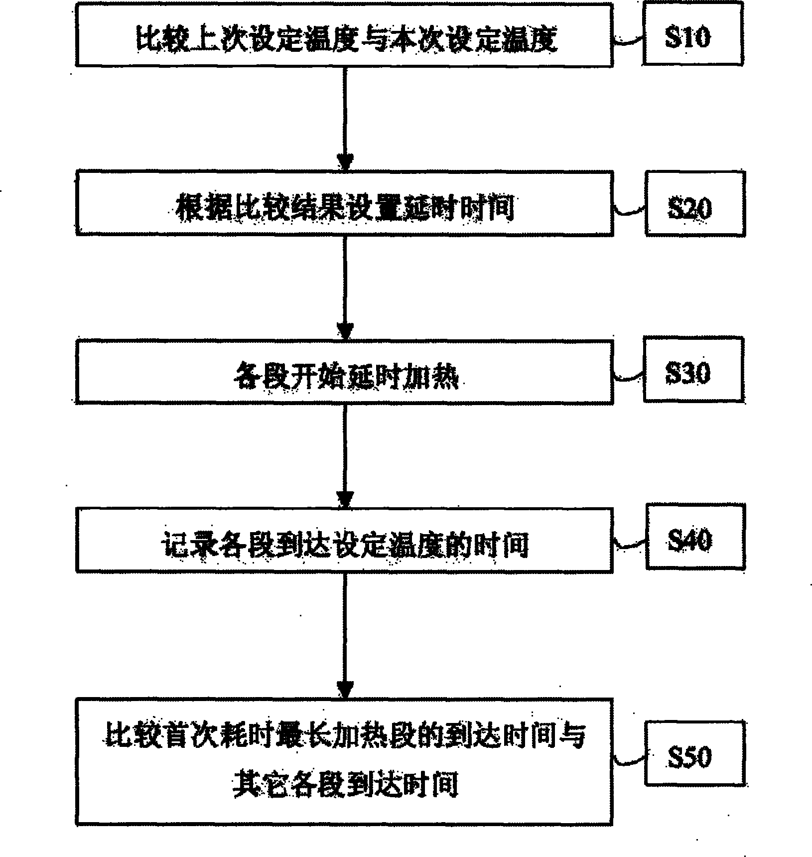
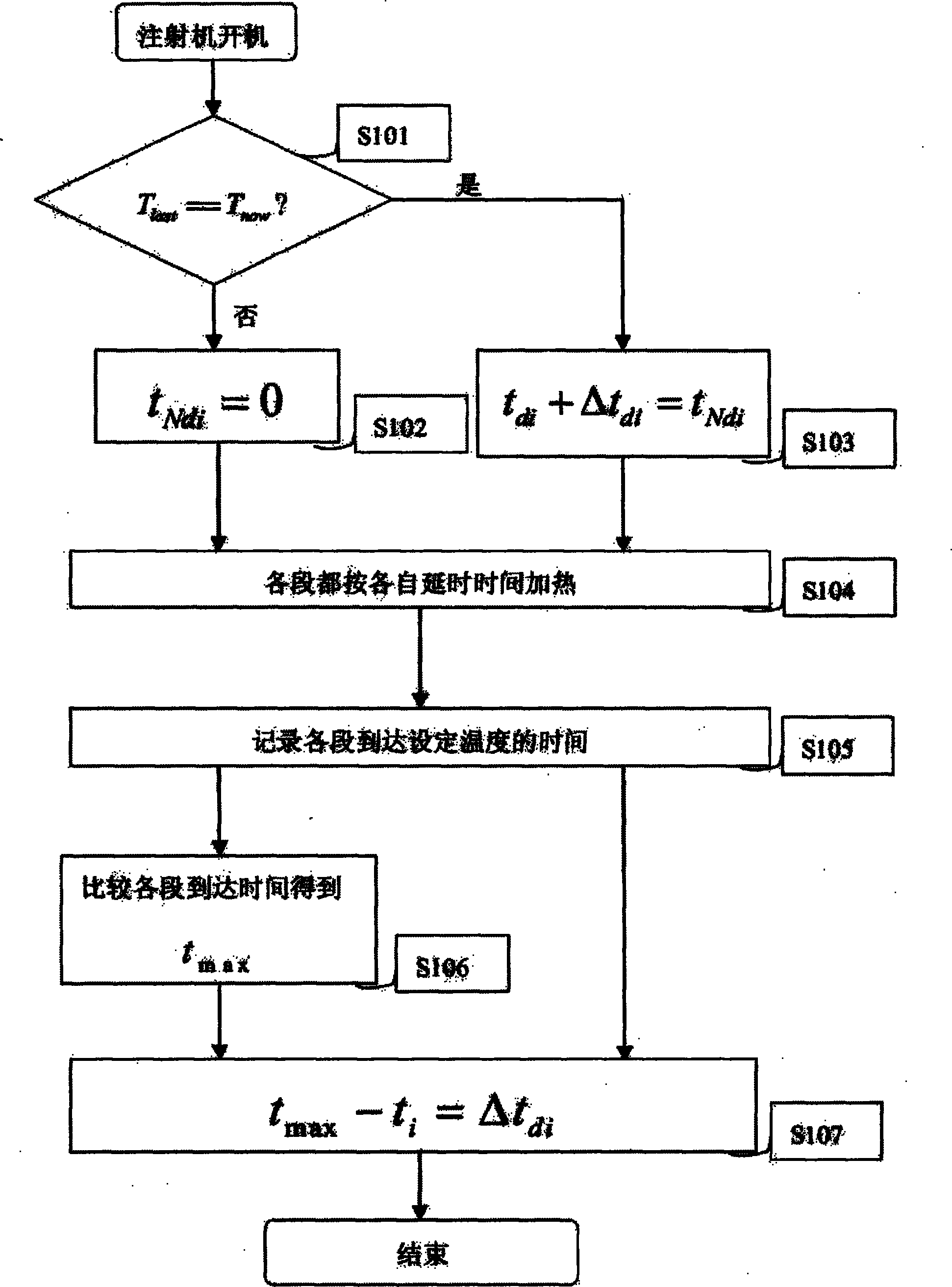
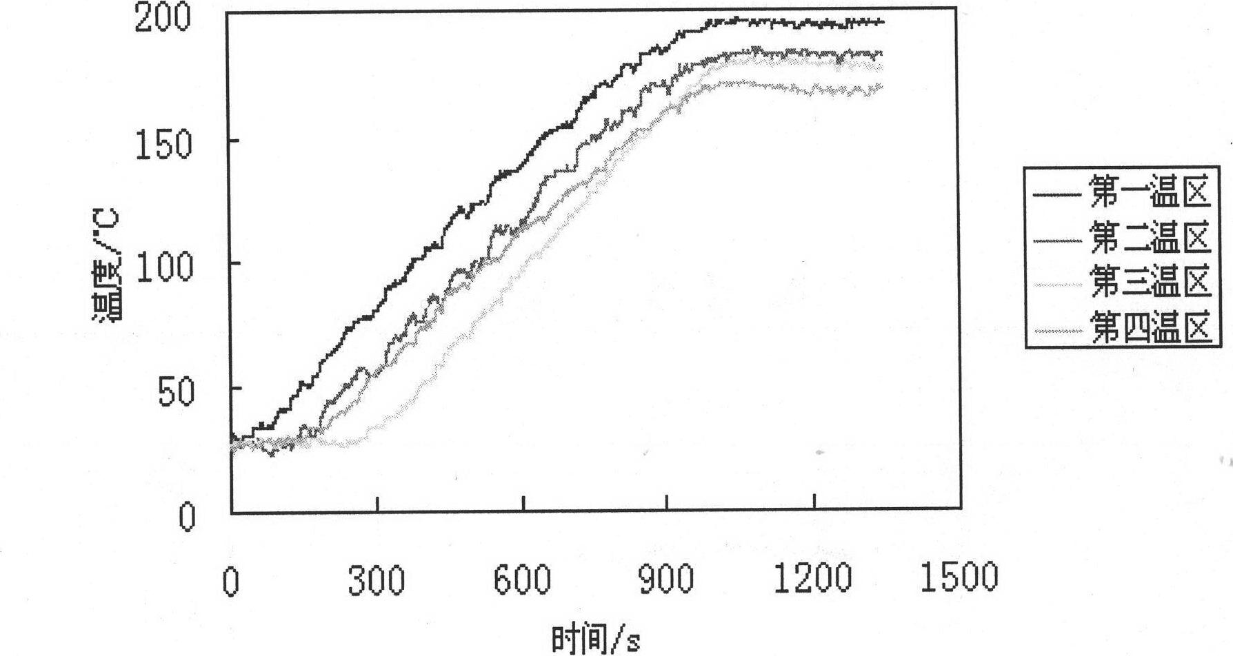
[0023] The specific implementation process of the temperature control method for isochronously reaching the set temperature in the preheating stage of the present invention will be described in detail in conjunction with each accompanying drawing.

[0024] refer to figure 1 , this figure is a flow chart of the main realization process of the isochronous arrival of the set temperature temperature control method in the preheating stage of the plastic mechanical barrel and the head mold of the present invention. The main process of utilizing the present invention to control the temperature of the plastic machinery barrel and the mold of the die is as follows:

[0025] Step S10, when the system is turned on, compare the set temperature T now Compared with the last boot set temperature T last , judging whether the two set temperatures are exactly the same T last = = ? T ...


PUM


Abstract

The invention relates to a temperature control method for reaching a set temperature at equal time intervals at the preheating stage of plastic machinery, in particular to a temperature control method for realizing various stages of a charging barrel and a handpiece die of the plastic machinery to reach a set temperature at equal time intervals by using a delay heating method on an original temperature control system, and the system temperature is controlled by the temperature control method provided by the invention before being controlled by a system PID (Proportion Integration Differentiation) or a fuzzy PID. The method mainly comprises the following steps of: firstly, finding a heating segment with the longest first time duration and recording times for various segments to reach the set temperature; and then, respectively subtracting the arrival times of other segments from the arrival time of the heating segment with the longest first time interval so as to acquire respective next heating delay times. The delay times are more accurate in the later boot process, the self adaptivity of the delay times is realized, the heat energy loss of the segments with low set temperatures because of waiting segments with the set temperatures for reaching the set temperature is avoided, the meaningless electricity waste on temperature control equipment is decreased, and the aim of energy saving is achieved.

Description

technical field [0001] The invention relates to a temperature control method in the preheating stage of plastic machinery, which belongs to the field of temperature control of precision molding machines for plastic products. Background technique [0002] The plasticizing device of the injection molding machine and the extrusion device of the extruder are equipment that heat and melt the plastic raw material and inject it into the mold or extrude it through the machine head, and then cool and shape it into a plastic product. Its barrel and mold temperature have an important influence on product performance and quality. If the temperature is too high, the plastic will decompose; if the temperature is too low, the plastic will be poorly plasticized, the fluidity will be poor, and the product will not be formed well, so the plastic melt temperature is too low or too high will affect the final quality of the product. At the same time, different raw materials have different optim...

Claims


Application Information

Patent Timeline
IPC IPC(8): B29C45/78B29C47/92B29C48/92
CPCB29C48/92B29C2948/92704B29C2948/92895
Inventor 杨卫民常士家何雪涛谢鹏程丁玉梅
Owner BEIJING UNIV OF CHEM TECH
Learn More