Power amplifier circuit, control method and earphone system
A technology of a power amplifier circuit and a control method, which is applied in the direction of earpiece/headphone accessories, headphone mechanical/electronic switches, electrical components, etc., can solve the problems of high requirements on the wearing state, and achieve the effect of self-adaptation and good use effect
- Summary
- Abstract
- Description
- Claims
- Application Information
AI Technical Summary
Problems solved by technology
Method used
Image
Examples
Embodiment 1
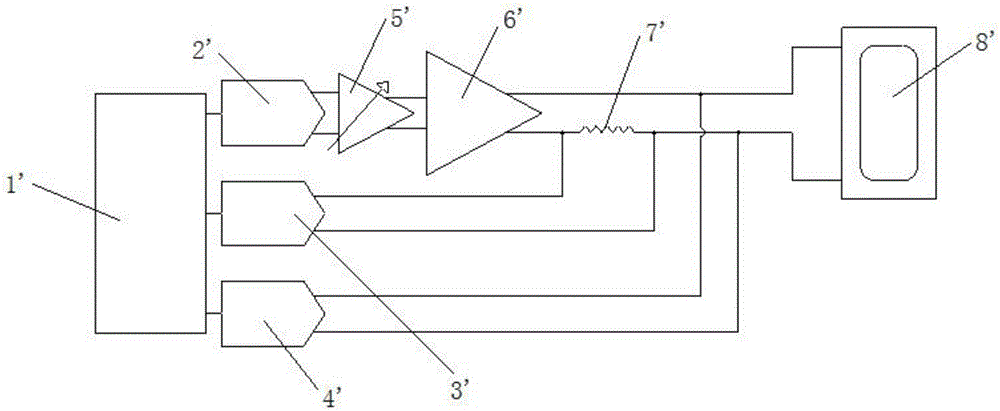
[0063] The intelligent power amplifier system is a system that implements nonlinear digital control and protection in audio signal processing. It is mostly used to protect electro-acoustic transducer systems such as speakers and effectively prolong their service life. The simplified circuit diagram of the traditional intelligent power amplifier is as follows: figure 1 As shown, the signal output module 2' outputs the sound signal to the speaker 8' through the variable gain amplifier 5' and the power amplifier 6' to make it sound and work. The purpose of the voltage detection unit 4' and the current detection unit 3' is to detect the Voltage, current, and based on this result to infer the working state of the speaker, and then feed the information back to the signal processor. The signal processor 1' changes the output signal and transmits it to the signal output module 2' by filtering or adjusting the voltage. The final audio signal output to the loudspeaker can be adjusted i...
Embodiment 2
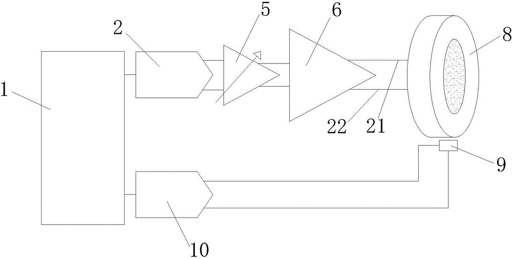
[0068] The active noise reduction headphone system includes a headphone, a microphone and a noise reduction circuit. The microphone collects the noise signal of the external environment, and the noise reduction circuit generates a noise reduction signal with the same amplitude and opposite phase as the noise signal according to the noise signal and outputs it to the earphone, the earphone receives the noise reduction signal and makes a sound, which cancels out the external noise to achieve noise reduction Effect.
[0069] Install the mems microphone originally used for noise reduction to the sound hole of the earphone, and input a frequency sweep signal with an amplitude of 179mVrms to the earphone, and the sweep frequency range is 20-20kHz, and then the frequency response detection result of the signal sent by the earphone can be obtained. Figure 4 It is the test result of the frequency response curve of an in-ear headphone under different leakage states. Figure 4 The midd...
Embodiment 3
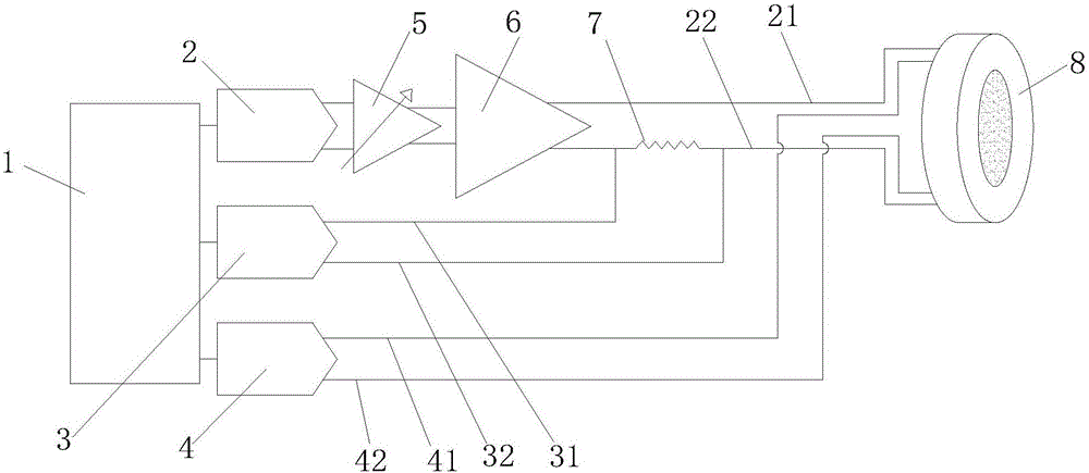
[0075] This embodiment provides an earphone system, which includes an earphone 8 and the power amplifier circuit as described in the first embodiment.
[0076] Wherein, the earphone 8 includes a first positive pole 81 , a first negative pole 82 , a second positive pole 83 and a second negative pole 84 . The voltage detection positive pole 41 is connected to the first positive pole 81 , the voltage detection negative pole 42 is connected to the first negative pole 82 , and the voltage detection unit 4 detects the voltage of the speaker 8 through the first positive pole 81 and the first negative pole 82 . The signal positive electrode 21 is connected to the second positive electrode 83 , and the signal negative electrode 22 is connected to the second negative electrode 84 . The signal output module 2 inputs signals to the earphone 8 through the second positive pole 83 and the second negative pole 84 to drive it to produce sound.
[0077] The arrangement of the first positive po...
PUM
 Abstract
Description
Claims
Application Information
 - R&D
- Intellectual Property
- Life Sciences
- Materials
- Tech Scout
- Unparalleled Data Quality
- Higher Quality Content
- 60% Fewer Hallucinations
Browse by: Latest US Patents, China's latest patents, Technical Efficacy Thesaurus, Application Domain, Technology Topic, Popular Technical Reports.
© 2025 PatSnap. All rights reserved.Legal|Privacy policy|Modern Slavery Act Transparency Statement|Sitemap|About US| Contact US: help@patsnap.com


