
Device and method for separating printed products out of a stack

A printing product and separate printing technology, which is applied in the field of separating printed products from stacks, can solve problems such as inability to adjust movement, stuck printed products, expensive transmission systems, etc., and achieve the effect of protecting printed products

Inactive Publication Date: 2011-06-22
MULLER MARTINI HLDG
View PDF13 Cites 11 Cited by
  • Summary
  • Abstract
  • Description
  • Claims
  • Application Information

AI Technical Summary

Problems solved by technology

The mass to be accelerated is relatively large, which also makes the frame of the device have to withstand excessive forces
Furthermore, pairs of take-off rollers that are fixedly adjusted relative to each other are not suitable for the processing of perfect-bound catalogs with coated backs.
Finally, there is a risk of the remaining stack tipping over to one side when separating the lowermost printed sheet
[0008] The problem with these known solutions is that the movement during the movement is predetermined, so that the acceleration of the printed product cannot be optimized for efficient separation
In addition, the speed situation at the point of transfer, especially when the product is transferred from the mobile gantry to the conveyor rollers, is unfavorable, so that the quality of the printed product is often compromised
Since the movement conditions predetermined by this mechanism are fixed, it is not possible to adapt the movement to the corresponding format of the printed products to be separated
The remaining stack slides uncontrollably on top of each other, causing the problem that the printed products get stuck in the storage drum, which prevents a process-reliable separation
Solutions that allow flexible specification of the motion profile and output speed of the mobile gantry require expensive drive trains with power and control lines moving together, however this is not suitable for high efficiency e.g. more than 15000 jobs per hour Persistence of the cycle

Method used


Image

  • Device and method for separating printed products out of a stack
  • Device and method for separating printed products out of a stack
  • Device and method for separating printed products out of a stack

Examples


Embodiment Construction

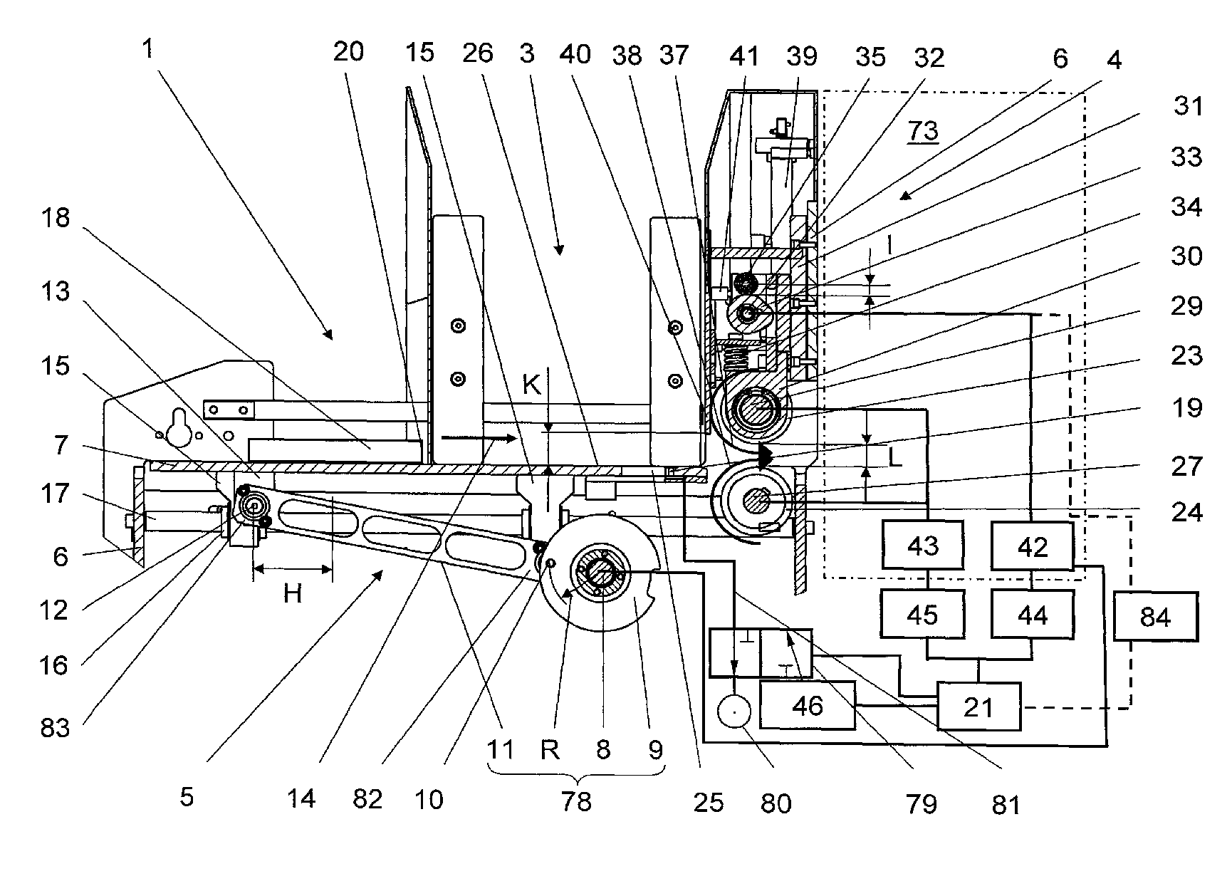
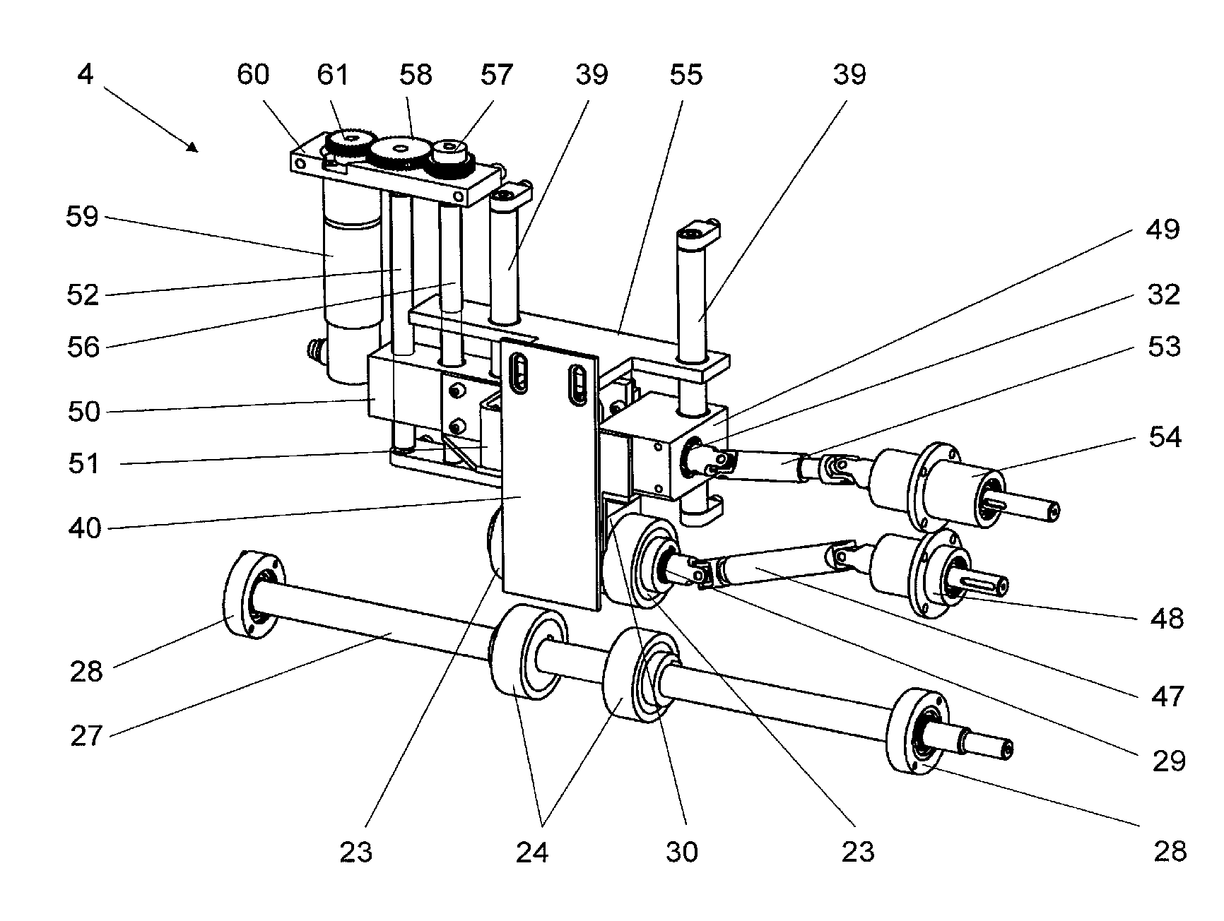
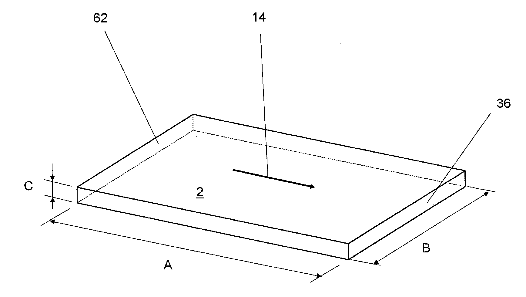
[0038] figure 1 shown for printing products 2, 2a, 2b, 2c ( image 3 , Figures 6a-6f ) of the separating device 1, the separating device is mainly composed of a material box 3, a conveying device 4 and a moving device 5, which are respectively fixed on the frame 6. The frame 6 is, for example, a welded structure with a plurality of parts, but may also have joint parts that are screwed to each other, or a cast structure.

[0039] The mobile device 5 comprises a mobile stage 7 and the components required for the translational vibrational movement of the mobile stage. One such component is the drive shaft 8 to which a crank disk 9 is fastened, which in turn is rotatably coupled to the first end 82 of the connecting rod 11 via the first shaft 10 . The opposite second end 83 of the connecting rod 11 is rotatably connected via the second shaft 12 to the first holder 13 , which is itself fixed on the moving table 7 . In order to achieve an oscillatory translational movement of t...


PUM


Abstract

The invention relates to a device for separating printed products (2) out of a stack (77). The device has a moving equipment (5) used for separating printed products (2) and a post-positioned conveying equipment (4) used for conveying the separated printed products (2); wherein the moving equipment (5) and the conveying equipment (4) respectively has a transmission mechanism (42, 43) which rotate independently of each other. Thereby the moving equipment (5) and the conveying equipment (4) are rotated and driven independently of each other; and the printed products (2, 2a, 2b, 2c) are accelerated to a first speed in the moving equipment (5), and are accelerated to a second speed which is higher than the first speed in the conveying equipment (4).

Description

technical field [0001] The invention relates to a method and a device for separating printed products from a stack, the device having a moving device for separating printed products and a downstream conveyor device for conveying the separated printed products. Background technique [0002] In order to separate printed products from the magazine, in particular those with a thickness of more than about 2 mm bound for a perfect binding, so-called sliding feeders are usually used, which consist of a mobile device and a subsequent conveying device. With this technique, the separation efficiency is limited due to the relatively large mass to be moved through a corresponding stroke of the mobile device. Interfering streaks also appear on these printed products due to the jump in speed of the printed products as they are transferred from the mobile device to the conveyor device. [0003] A separating device is known from DE 1247266, with which a book or paperback is output from a s...

Claims


Application Information

Patent Timeline
Patent Type & Authority Applications(China)
IPC IPC(8): B65H3/00B65H3/64
CPCB65H2404/1441B65H2557/242B65H2513/512B65H2511/20B65H2515/342B65H2513/11B65H7/18B65H2515/32B65H2513/21B65H2403/532B65H2404/152B65H2513/104B65H2511/11B65H3/24B65H2511/224B65H3/122B65H2513/10B65H5/062B65H2513/20B65H2515/34B65H2220/01B65H2220/11B65H2220/02B65H2220/03
Inventor C.吉辛P.米勒A.赫斯
Owner MULLER MARTINI HLDG
Learn More