Method for depositing back electrode in solar cell production

A technology of solar cells and deposition methods, which is applied in the field of solar cell production, can solve problems such as the influence of the next process, low target utilization rate, and increased scrap rate, so as to achieve short vacuuming time, reduce production and maintenance costs, and utilize rate-enhancing effect

Inactive Publication Date: 2011-06-22
JILIN QINGDA NEW ENERGY ELECTRIC POWER
View PDF0 Cites 1 Cited by
  • Summary
  • Abstract
  • Description
  • Claims
  • Application Information

AI Technical Summary

Problems solved by technology

[0004] Most of the existing sputtering back electrode equipment is a horizontal structure planar sputtering back electrode. There are many shortcomings and deficiencies in the sputtering back electrode equipment with the above structure. , the efficiency is slow, the target usage rate is low, and there are residues left on the battery surface after sputtering, which will affect the next process and increase the waste rate

Method used


Image

  • Method for depositing back electrode in solar cell production
  • Method for depositing back electrode in solar cell production
  • Method for depositing back electrode in solar cell production

Examples


Embodiment Construction

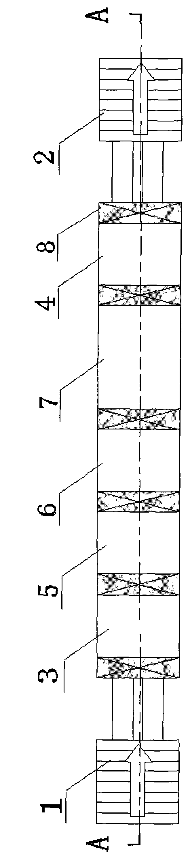
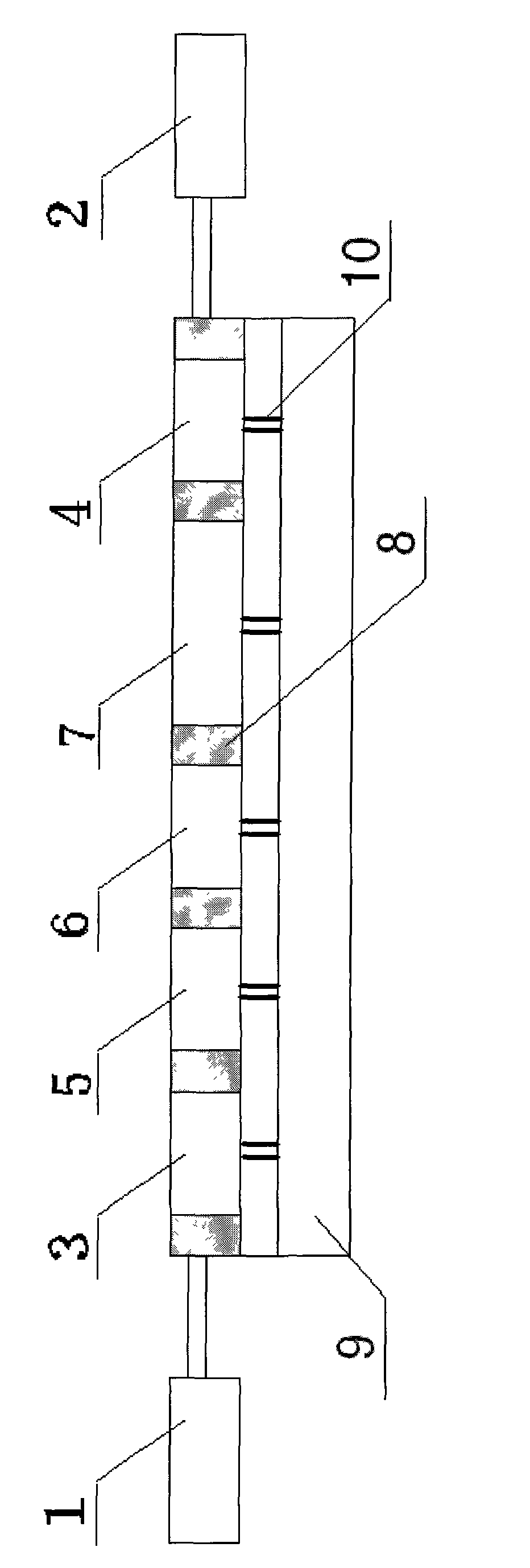
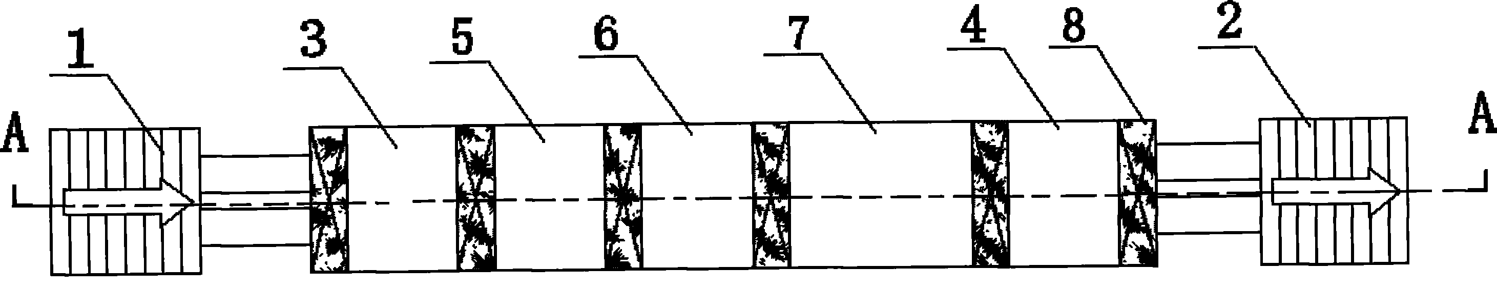
[0011] attached by figure 1 , 2 Shown: this method is to adopt the magnetron sputtering equipment of sputtering back electrode on the back of solar cell to realize through the following steps, described magnetron sputtering equipment is a tunnel type structural form, and it comprises sheet-feeding stage 1, exits Chip stage 2, buffer chambers 3, 4, heating chambers 5, 6, sputtering chamber 7, the buffer chambers 3, 4, heating chambers 5, 6, sputtering chamber 7 between each chamber Separated by a valve 8, two buffer chambers 3 and 4 arranged at both ends, two heating chambers 5 and 6 arranged side by side in the middle and a sputtering chamber 7 constitute the main body of the magnetron sputtering equipment. A vacuum system 9 is provided below each chamber of the main body of the injection equipment. The vacuum system 9 is connected to the buffer chambers 3, 4, the heating chambers 5, 6 and the sputtering chamber 7 through a vacuum pipeline 10.

[0012] The specific steps of ...


PUM


Abstract

The invention relates to the field of production of solar cells, in particular to a method for depositing a back electrode in solar cell production. The method is implemented by special magnetron sputtering equipment for sputtering the back electrode on the back face of a solar cell by the following steps of: firstly, introducing two cell slices into a buffer cabin every time through a slice inlet platform under the driving action of a conveying guide rail on which a cell slice suspension box is hung, and making the cell slices continually move forward into two heating cabins in turn, wherein the heating temperature of one heating cabin into which the cell slices moves earlier is 35 DEG C, the heating temperature of the other second heating cabin into which the cell slices moves later is 50 DEG C, and the temperature is up to 50 DEG C after twice heating; and making the cell slices enter a sputtering cabin, uniformly sputtering an Al layer serving as the back electrode in the sputtering cabin by a magnetron sputtering principle, discharging the cell slices out of the cabin, and making the cell slices enter next equipment through a buffer cabin and a cell slice outlet platform, wherein a vacuum system connected to each cabin through a vacuum pipeline is used for controlling the vacuum value of each cabin, and a valve is used for partitioning each cabin into relatively independent spaces, so that the aim of sputtering the back electrode of the solar cell is fulfilled.

Description

technical field [0001] The invention relates to the field of solar cell production, in particular to a magnetron sputtering device for sputtering a back electrode on the back of a solar cell to realize the deposition method of the back electrode in solar cell production. Background technique [0002] In the production process of amorphous silicon thin-film batteries, an important step is to deposit the back electrode after depositing the PIN layer as the power generation layer. The back electrode is used as one of the electrodes of the battery and can collect the current at every point on the battery. Increase the short-circuit current and improve the conversion efficiency of the battery, thereby improving the stability of the battery and the performance of the battery. [0003] And because the conversion efficiency of the amorphous silicon thin film solar cell is low, the performance is not stable enough, and there is a phenomenon of light-induced degradation, the light abs...

Claims


Application Information

Patent Timeline
Patent Type & Authority Applications(China)
IPC IPC(8): C23C14/35
Inventor 杨继泽刘万学张兵王巍左腾杜宏荀魏含芳杨帅
Owner JILIN QINGDA NEW ENERGY ELECTRIC POWER
Why Eureka
Try Eureka