Vibration damping device of gear transmission flywheel
A technology of vibration damping device and gear transmission, which is applied in the direction of transmission device, friction transmission device, transmission device parts, etc., can solve the problems of increasing the cost of vibration control, etc., and achieve the improvement of vibration reduction effect, increase of frictional damping effect, and cost reduction Effect
- Summary
- Abstract
- Description
- Claims
- Application Information
AI Technical Summary
Problems solved by technology
Method used
Image

Examples
Embodiment 1
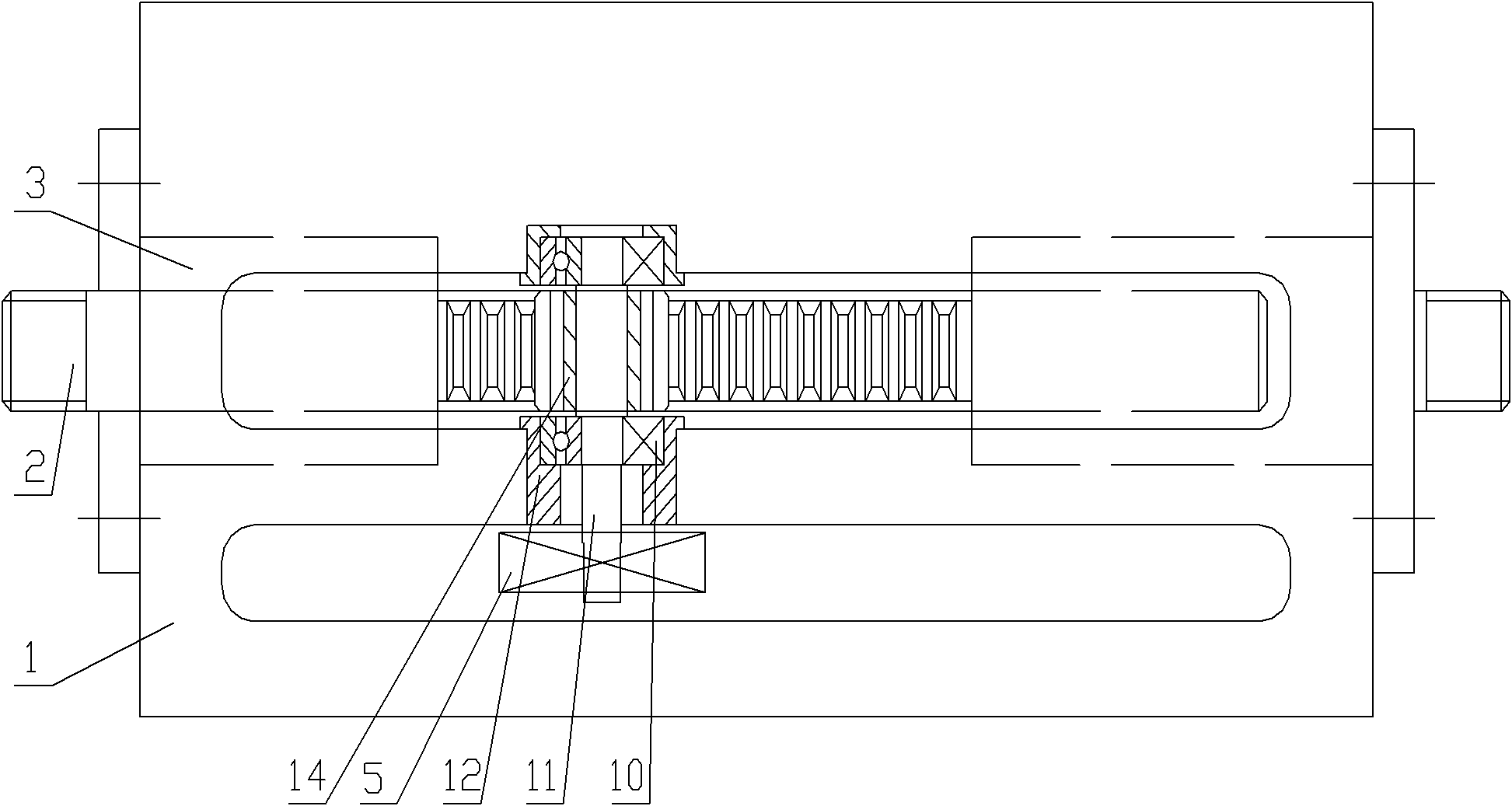
[0039] see figure 1 , figure 1 It is a schematic structural diagram of the gear transmission flywheel damping device provided by Embodiment 1 of the present invention.
[0040] Wherein, 1 is a casing, 2 is a rack, 3 is a linear bearing, 5 is a flywheel, 10 is a bearing, 11 is a first transmission shaft, 12 is a bearing seat, and 14 is a first gear.
[0041] The geared flywheel damping device provided by Embodiment 1 of the present invention includes a box body 1 , a rack 2 , a first transmission shaft 11 , a first gear 14 and a flywheel 5 . Wherein, the box body 1 is the bearing and receiving part of the vibration damping device, and the racks 2 are erected at both ends of the box body 1 for receiving the vibration of reciprocating linear motion. The first transmission shaft 11 is arranged in the box body 1 through the bearing 10 . One end of the first transmission shaft 11 is provided with a first gear 14 meshing with the rack 2 , and the other end is provided with a flywhe...
Embodiment 2
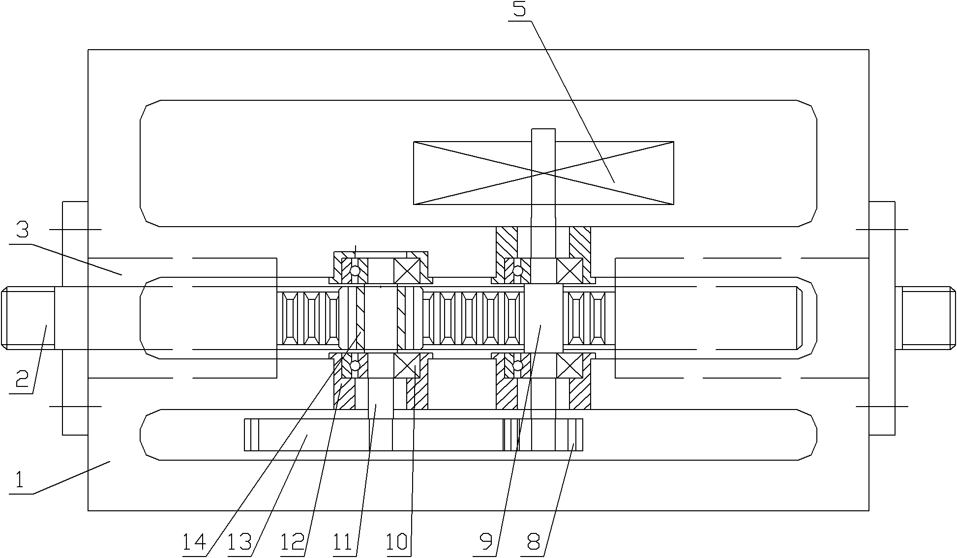
[0047] see figure 2 , figure 2 It is a schematic structural diagram of the gear drive flywheel damping device provided in Embodiment 2 of the present invention.
[0048] Among them, 1 is the box, 2 is the rack, 3 is the linear bearing, 5 is the flywheel, 8 is the third gear, 9 is the second transmission shaft, 10 is the bearing, 11 is the first transmission shaft, 12 is the bearing seat, 13 is the second gear, and 14 is the first gear.
[0049]The gear transmission flywheel damping device provided by Embodiment 2 of the present invention includes a box body 1 , a rack 2 , a first transmission shaft 11 , a second transmission shaft 9 and a flywheel 5 . Wherein, the box body 1 is the bearing and receiving part of the vibration damping device, and the racks 2 are erected at both ends of the box body 1 for receiving the vibration of reciprocating linear motion. The first transmission shaft 11 is arranged in the box body 1 through the bearing 10 , one end of the first transmis...
Embodiment 3
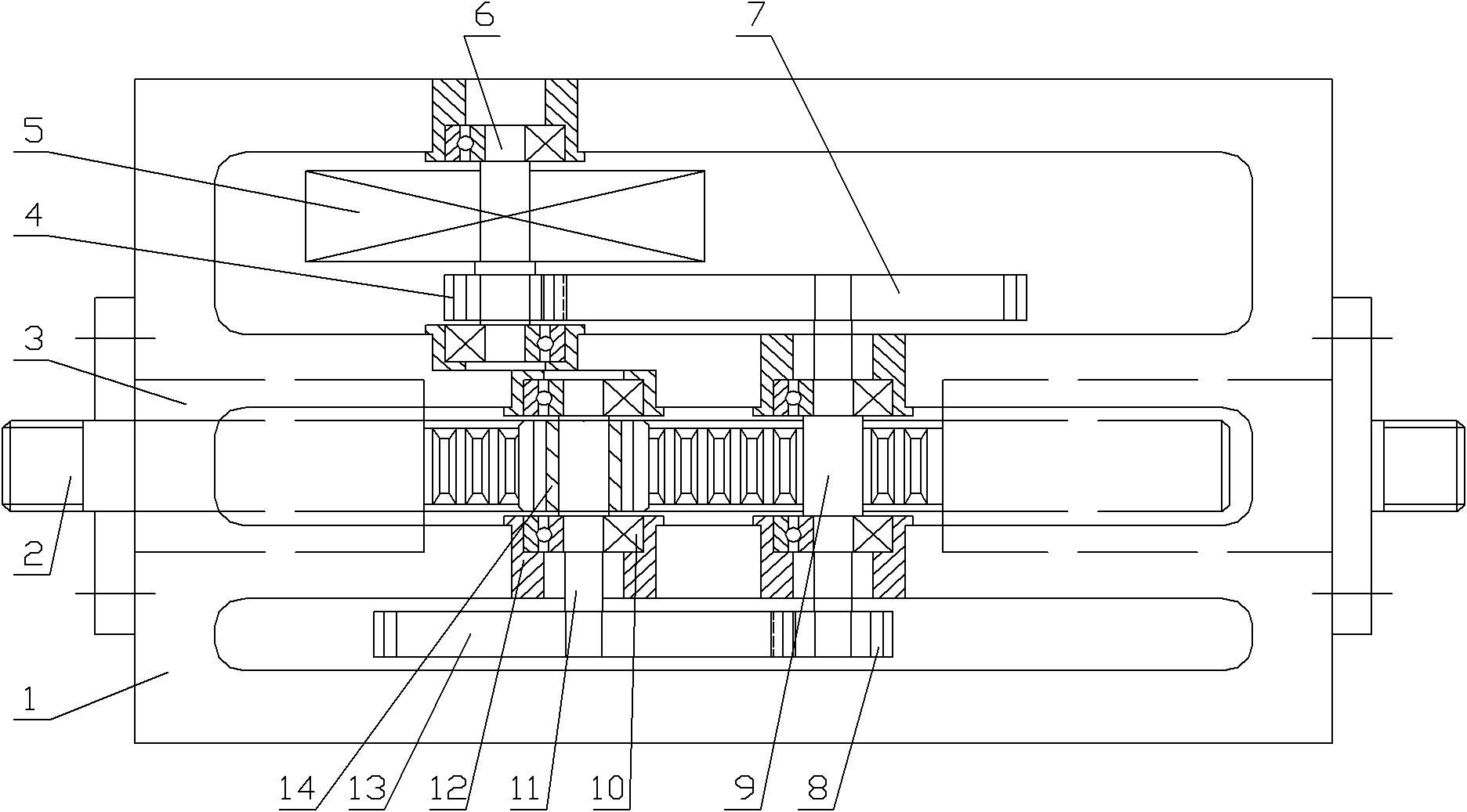
[0055] see image 3 , image 3 It is a schematic structural diagram of a vibration damping device for a gear transmission flywheel provided by Embodiment 3 of the present invention.
[0056] Among them, 1 is the box, 2 is the rack, 3 is the linear bearing, 4 is the fifth gear, 5 is the flywheel, 6 is the third transmission shaft, 7 is the fourth gear, 8 is the third gear, 9 is the second gear Transmission shaft, 10 is a bearing, 11 is a first transmission shaft, 12 is a bearing seat, 13 is a second gear, and 14 is a first gear.
[0057] The gear drive flywheel damping device provided by Embodiment 3 of the present invention includes a box body 1 , a rack 2 , a first transmission shaft 11 , a second transmission shaft 9 , a third transmission shaft 6 and a flywheel 5 . Wherein, the box body 1 is the bearing and receiving part of the vibration damping device, and the racks 2 are erected at both ends of the box body 1 for receiving the vibration of reciprocating linear motion. ...
PUM
 Abstract
Description
Claims
Application Information
 - R&D
- Intellectual Property
- Life Sciences
- Materials
- Tech Scout
- Unparalleled Data Quality
- Higher Quality Content
- 60% Fewer Hallucinations
Browse by: Latest US Patents, China's latest patents, Technical Efficacy Thesaurus, Application Domain, Technology Topic, Popular Technical Reports.
© 2025 PatSnap. All rights reserved.Legal|Privacy policy|Modern Slavery Act Transparency Statement|Sitemap|About US| Contact US: help@patsnap.com