Cylindrical double-layer winding linear permanent magnet synchronous generator

A double-layer winding, permanent magnet synchronous technology, applied in electrical components, electromechanical devices, etc., can solve problems such as limiting motor efficiency and permanent magnet utilization, increasing secondary weight of iron core, reducing motor response speed, etc., to improve power quality. , the effect of reducing secondary quality and improving response speed

Active Publication Date: 2011-06-22
ZHEJIANG SCI-TECH UNIV
3 Cites 5 Cited by

AI-Extracted Technical Summary

Problems solved by technology

[0004] 1. The cogging effect of the motor will generate positioning force, which affects the stability of the motor operation;
[0005] 2. The existence of the iron core increases t...

Method used

[0022] As shown in the accompanying drawings, the present invention includes an outer cylinder that is provided with a shaft 6 of a plurality of circular permanent magnets 3 and an outer core 1-1 that is wound with an outer winding 2-1 in the inner hole. The circular permanent magnets 3 are separated by the first group of magnetic spacer rings 5 ​​. The number of the outer layer winding 2-1 is the same as that of the 3 annular permanent magnets, and they are separated from each other by the second group of magnetic spacer rings 5 ​​. The shaft 6 is coaxially installed in the hole of the outer core 1-1. There is a center hole in the center of the shaft 6, and the inner layer iron core 1-2 is installed from one end of the shaft 6 with the center hole into the center hole, and the inner layer winding 2 is wound on the outer cylinder of the inner layer iron core 1-2. -2. The number of the inner layer winding 2-2 is the same as that of the 3 annular permanent magnets, and they are separated from each other by the third group of magnetic spacer rings 5 ​​. Both sides of the ma...

Abstract

The invention discloses a cylindrical double-layer winding linear permanent magnet synchronous generator. The cylindrical double-layer winding linear permanent magnet synchronous generator comprises shafts and outer iron cores, wherein the outer cylinders of the shafts are provided with a plurality of annular permanent magnets and the shafts are spaced from each other by using a first group of magnetic separation rings; and a plurality of outer windings in the same number as the annular permanent magnets are wound around the inner holes of the outer iron cores and the outer iron cores are spaced from each other by using a second group of magnetic separation rings. The centers of the shafts are provided with central holes; inner iron cores are arranged in the central holes; the outer cylinders of the inner iron cores are provided with inner windings which are spaced from each other by using a third group of magnetic separation rings; a spring is arranged between the inside surface of the inner iron cores and the shaft bottom surfaces of the central holes; end covers are arranged on the inner iron cores and the outer iron cores; and annular air gaps with the same height are reservedamong the outer windings, the permanent magnets and the inner windings respectively. The cylindrical double-layer winding linear permanent magnet synchronous generator adopts a slotless moving-magnetic type dual-stator structure, eliminates positioning force, and simultaneously has the characteristics of quick response, high permanent magnet utilization rate and the like, does not need an intermediate conversion device, converts rectilinear motion into electric quantity and outputs the electric quantity, can be used in the fields such as pistons, wave power generation and the like, saves energy and is environmentally-friendly.

Application Domain

Technology Topic

Image

  • Cylindrical double-layer winding linear permanent magnet synchronous generator
  • Cylindrical double-layer winding linear permanent magnet synchronous generator

Examples

  • Experimental program(1)

Example Embodiment

[0021] The present invention will be further described below in conjunction with the accompanying drawings and embodiments.
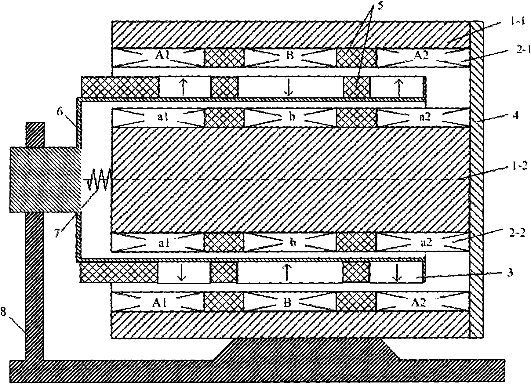
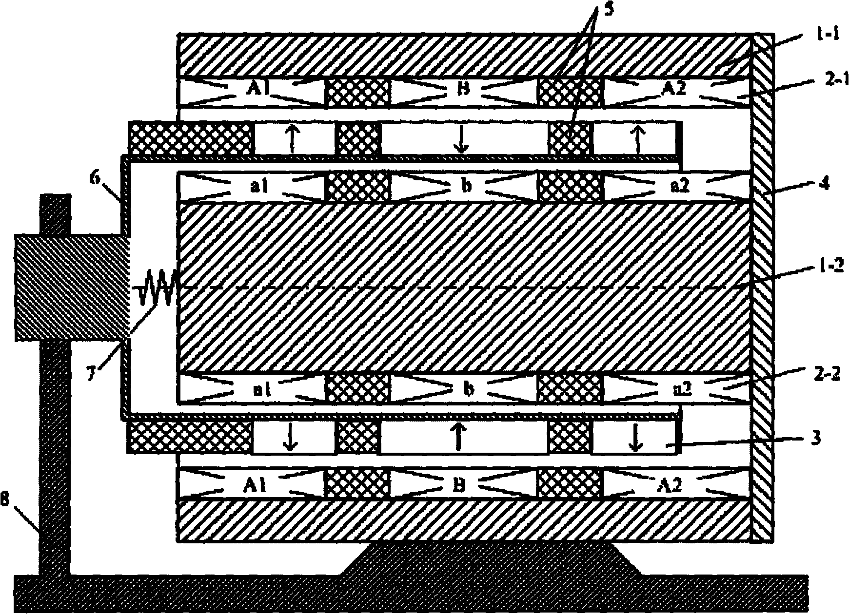
[0022] As shown in the accompanying drawings, the present invention includes a shaft 6 with a plurality of annular permanent magnets 3 arranged on an outer cylinder and an outer core 1-1 with an outer winding 2-1 around the inner hole. The circular permanent magnets 3 are separated by the first group of magnetic spacer rings 5 ​​. The number of the outer layer winding 2-1 is the same as that of the 3 annular permanent magnets, and they are separated from each other by the second group of magnetic spacer rings 5 ​​. The shaft 6 is coaxially installed in the hole of the outer core 1-1. There is a center hole in the center of the shaft 6, and the inner layer iron core 1-2 is installed from one end of the shaft 6 with the center hole into the center hole, and the inner layer winding 2 is wound on the outer cylinder of the inner layer iron core 1-2. -2. The number of the inner layer winding 2-2 is the same as that of the 3 annular permanent magnets, and they are separated from each other by the third group of magnetic spacer rings 5 ​​. Both sides of the magnetic isolation ring 5 are provided with grooves, which can play a role in fixing the outer layer winding 2-1 and the inner layer winding 2-2. The spring 7 is installed between the inner surface of the inner core 1-2 and the bottom surface of the shaft 6 with a central hole, which can relieve the external impact force and limit the secondary stroke. When the frequency of the external driving equipment is constant, the motor efficiency can also be improved through resonance. Effect. The outer surface of the inner layer iron core 1-2 and the end face of the outer layer iron core 1-1 are equipped with an end cover 4, and the end cover 4 is required to have a certain strength, thereby ensuring a good connection between the outer layer iron core 1-1 and the inner layer iron core 1-2. Concentricity. One end of the shaft 6 is fixed by a pillar 8 to ensure the coaxiality of the shaft 6 with the outer layer iron core 1-1 and the inner layer iron core 1-2, so that the permanent magnet 3 and the outer layer winding 2-1 and the inner layer winding 2-2 maintain the same air gap height.
[0023] The outer layer winding 2-1 and the inner layer winding 2-2 are formed by winding enamelled copper wires. The outer layer winding 2-1 includes three annular windings A1, B, A2, which are connected in series, wherein the windings A1, A2 at both ends have the same winding direction, and the middle winding B has the opposite direction; the inner layer winding 2-2 includes Three ring-shaped windings a1, b, a2 are connected in series, wherein the windings a1, a2 at both ends of the inner winding are in the same direction as the windings a1, a2 at the two ends of the outer winding, and the winding direction of the middle winding b is opposite; the outer winding and The inner windings are connected in series with each other.
[0024] The three annular permanent magnets 3 are radially magnetized rare earth permanent magnet neodymium-iron-boron magnets, the magnetization directions of adjacent annular permanent magnets are opposite, and two adjacent annular permanent magnets are placed between There is a magnetic isolation ring, and the magnetic field forms a loop through the inner layer iron core 1-1 and the outer layer iron core 1-2, and is distributed sinusoidally along the space.
[0025] The slot pitch of the outer layer winding and the slot pitch of the inner layer winding are equal to the pole pitch of the permanent magnet. The primary iron core is made of ordinary silicon steel sheet or A3 steel, and the manufacturing process is the same as that of the traditional linear motor.
[0026] The invention can utilize linear power such as pistons or sea waves to generate electricity. When in use, the generator outer core 1-1 and the pillar 8 need to be fixed on the equipment, and the installation direction is determined by the direction of the external driving force to ensure that the permanent magnet 3 can reciprocate in the axial direction. When the generator is running, the shaft 6 is externally connected to the external drive device or the axial displacement occurs with the movement of the equipment, and the permanent magnet 3 will move with the outer winding 2-1 and the inner winding 2-2, and the outer winding 2 -1 and the inner layer winding 2-2 simultaneously cut the lines of magnetic force to generate induced electromotive force, and when an external load is connected, external power supply can be realized. Compared with the traditional single-layer winding structure, the present invention can provide higher induced electromotive force while ensuring the sensitivity of the motor under the condition of the same volume of the permanent magnet, thereby improving the utilization rate of the permanent magnet.

PUM

no PUM

Description & Claims & Application Information

We can also present the details of the Description, Claims and Application information to help users get a comprehensive understanding of the technical details of the patent, such as background art, summary of invention, brief description of drawings, description of embodiments, and other original content. On the other hand, users can also determine the specific scope of protection of the technology through the list of claims; as well as understand the changes in the life cycle of the technology with the presentation of the patent timeline. Login to view more.

Similar technology patents

Classification and recommendation of technical efficacy words

  • Avoid loss
  • Improve power generation efficiency
Why Eureka
Try Eureka