Method for interpreting system messages by LTE (Long Term Evolution) terminal
A system message and terminal technology, which is applied in communication between multiple stations, electrical components, wireless communication, etc., can solve problems such as time-consuming, unfavorable terminals to quickly interpret system messages, and signal interaction to increase design complexity, etc., to reduce Design complexity, increase speed, reduce interaction effect
- Summary
- Abstract
- Description
- Claims
- Application Information
AI Technical Summary
Problems solved by technology
Method used
Image

Examples
specific Embodiment 1
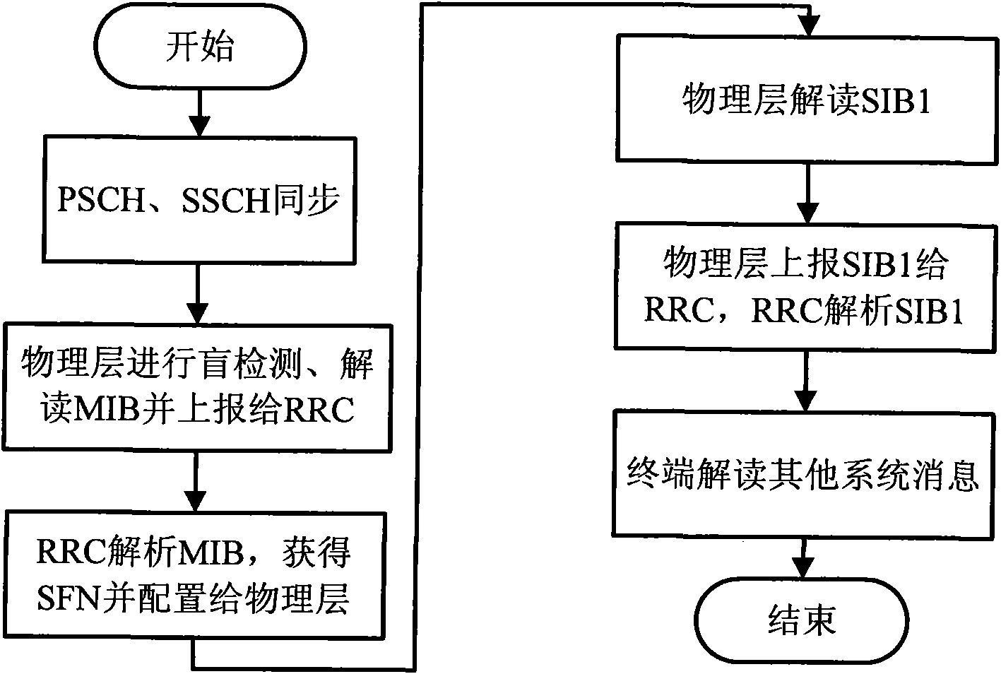
[0050] The process of this embodiment is attached Figure 4 Shown:
[0051] 1. The terminal performs PSCH and SSCH synchronization;
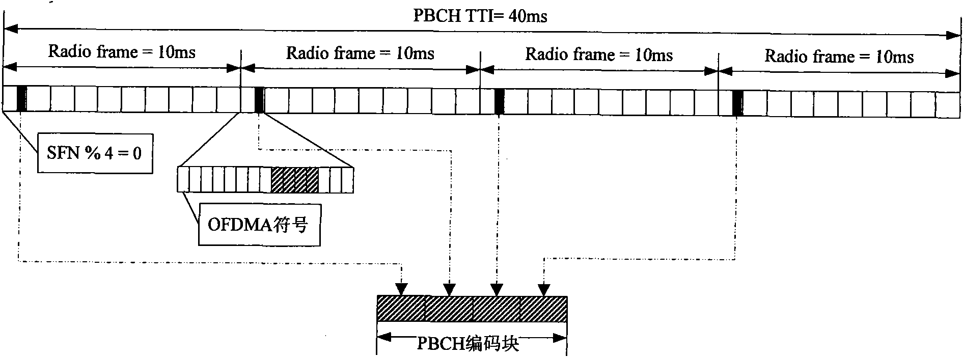
[0052] 2. The physical layer of the terminal performs PBCH blind detection to find the position of the wireless frame carrying the MIB data block;
[0053] 3. The physical layer interprets the MIB data block at the corresponding position;
[0054] 4. The physical layer analyzes all the contents of the MIB data block, obtains the upper 8 bits of the SFN of the wireless frame where the MIB data block is located, and obtains the SFN of the wireless frame where the MIB is located according to the time-frequency position rules of the MIB;
[0055] In this embodiment, after the physical layer parses the MIB data block, the upper 8 bits of the SFN of the wireless frame where the MIB is located are obtained. According to the MIB time-frequency position rule, the SFNs of the 4 wireless frames where the MIB is located are respectively: xxxxxxxx00, xxxxx...
specific Embodiment 2
[0060] The process of this embodiment is attached Figure 5 shown.
[0061] Steps 1~3 are identical with specific embodiment 1;
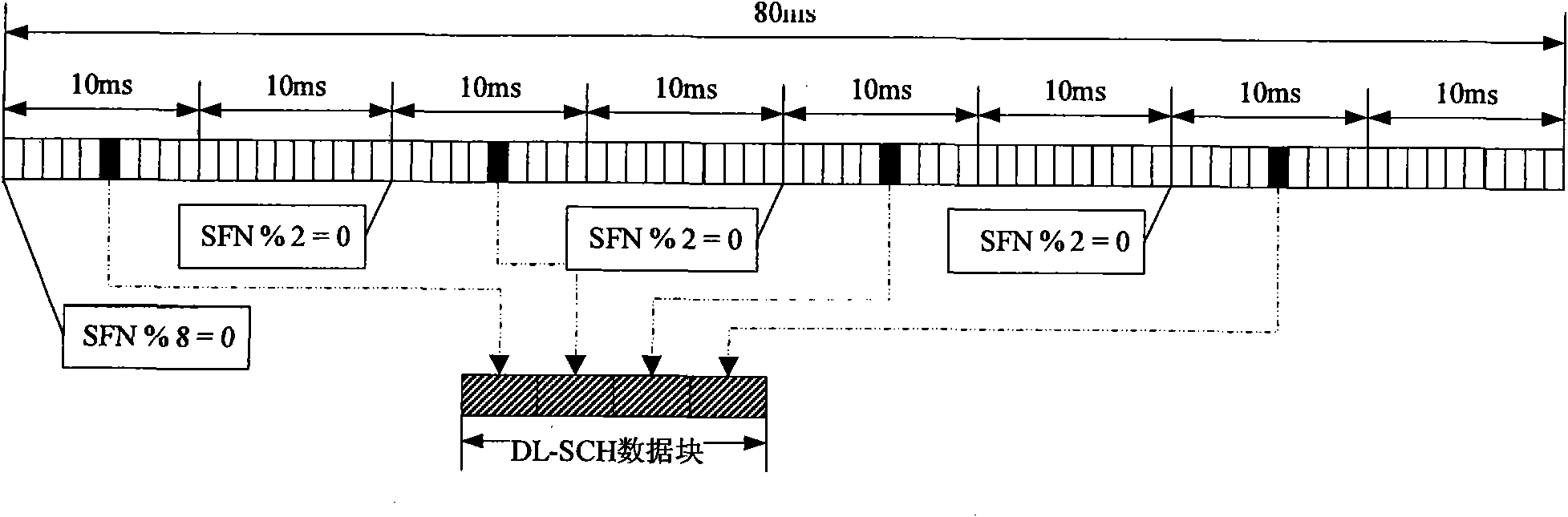
[0062] 4. The physical layer analyzes the SFN information in the MIB data block, obtains the upper 8 bits of the SFN of the wireless frame where the MIB data block is located, and obtains the SFN of the wireless frame where the MIB is located according to the time-frequency position rules of the MIB;
[0063] In this embodiment, the physical layer only parses the SFN data in the MIB data block, that is, starting from the 7th bit of the MIB data block, continuously reads 8 bits of data to obtain the upper 8 bits of the SFN of the wireless frame where the MIB is located, according to According to the MIB time-frequency position rule, the SFNs of the four wireless frames where the MIB is located are obtained in turn: xxxxxxxx00, xxxxxxxx01, xxxxxxxx10, xxxxxxxx11; where the frame number is represented in binary, and xxxxxxxx represents the upper 8 bit...
PUM
 Abstract
Description
Claims
Application Information
 - Generate Ideas
- Intellectual Property
- Life Sciences
- Materials
- Tech Scout
- Unparalleled Data Quality
- Higher Quality Content
- 60% Fewer Hallucinations
Browse by: Latest US Patents, China's latest patents, Technical Efficacy Thesaurus, Application Domain, Technology Topic, Popular Technical Reports.
© 2025 PatSnap. All rights reserved.Legal|Privacy policy|Modern Slavery Act Transparency Statement|Sitemap|About US| Contact US: help@patsnap.com