
Tank for working fluids of motor vehicles

A technology of working fluid and box body, which is applied in the direction of vehicle components, arrangement combined with internal combustion engine fuel supply, exhaust treatment, etc., to achieve the effect of improving the sealing effect

Inactive Publication Date: 2011-06-22
ALUTECH
View PDF5 Cites 0 Cited by
  • Summary
  • Abstract
  • Description
  • Claims
  • Application Information

AI Technical Summary

Problems solved by technology

[0003] The problem arises here that according to the conventional state of the art, parts of the metal wall are exposed in the region of the edges of the holes and can therefore be exposed to corrosive box contents, especially in During tank filling or shaking during normal work

Method used


Image

  • Tank for working fluids of motor vehicles
  • Tank for working fluids of motor vehicles
  • Tank for working fluids of motor vehicles

Examples


Embodiment Construction

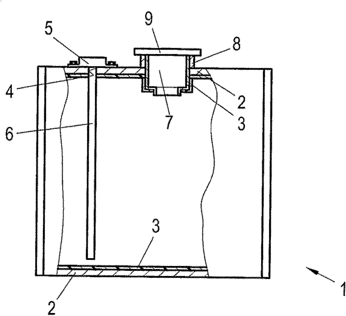
[0022] figure 1 Shown is a tank 1 which is intended to contain aggressive operating fluids of the motor vehicle, for example catalytic converter urea solution. The housing 1 can contain any built-in components such as partitions, splash guards, etc. for fuel, etc.

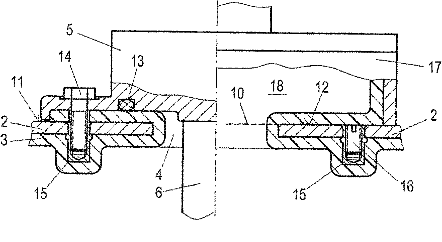
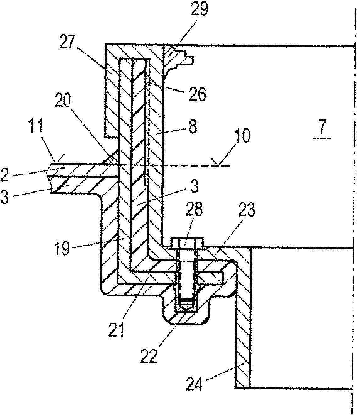
[0023] The housing 1 has a wall 2 made of metal, preferably aluminum. The metal wall 2 is provided on its inner side with a plastic coating 3 which thus lines the entire box interior.

[0024] The plastic coating 3 is resistant to the working fluid (here urea solution) to be accommodated. Suitable plastics for the plastic coating are, for example, polyolefins such as HPDE (high-density polyethylene), MDPE (medium-density polyethylene), LDPE (low-density polyethylene) or LLDPE (linear low-density polyethylene).

[0025] The plastic coating 3 is produced "in situ" on the metal wall 2 by means of rotational molding methods known in the prior art. For this purpose, the plastic material is introduced into the tank,...


PUM


Abstract

The invention relates to a tank (1) for working fluids of motor vehicles, comprising a metal wall (2), at least one opening (4, 7) therein, and a plastic coating (3) on the inside of the metal wall (2), wherein the plastic coating (3) extends through the opening (4, 7) at least to the level (10) of the outside (11) of the metal wall (2).

Description

technical field [0001] The invention relates to a tank for a working fluid of a motor vehicle comprising a metal wall, at least one hole in the metal wall and a plastic coating on the inner side of the metal wall. Background technique [0002] Metal tanks that need to be coated with plastic on the inside especially for aggressive automotive operating fluids such as urea It is used as a catalyst liquid for cleaning diesel exhaust. The plastic coating is usually formed in-situ inside the box by rotational molding. For this purpose, plastic particles are introduced into the tank through the holes, the holes are closed and the tank is turned while heating until the plastic melts evenly on the inside of the metal walls and forms a plastic coating there. The hole is then reopened. [0003] The problem arises here that, according to the conventional state of the art, parts of the metal wall are exposed in the region of the edges of the holes and can therefore be exposed to corr...

Claims


Application Information

Patent Timeline
IPC IPC(8): B60K15/03
CPCF01N2610/1413F01N2610/02F01N3/2066B60K2015/03557B60K2015/03039B60K13/04F01N2610/1406B60K2015/03348Y02A50/20
Inventor M·芒努松P·弗莱谢O·费尔德纳
Owner ALUTECH
Learn More