Injection mould provided wtih core-pulling mechanism driven by mould opening and closing actions

A technology of injection mold and core-pulling mechanism, which is applied in the field of improvement of the core-pulling mechanism in the mould, can solve problems such as core-pulling, and achieve the effects of saving processing costs, smooth action, and synchronous action

Active Publication Date: 2011-06-29
QINGDAO HAIER MOLDS
View PDF5 Cites 3 Cited by
  • Summary
  • Abstract
  • Description
  • Claims
  • Application Information

AI Technical Summary

Problems solved by technology

[0009] The invention provides an injection mold with a core-pulling mechanism driven by mold opening and closing, which can solve the problem that the undercut inside the product cannot be core-pulled by conventional methods such as inclined tops, and can realize the complexity of the mechanism, cost, stability, Improvements in production cycle, daily maintenance, etc.

Method used


Image

  • Injection mould provided wtih core-pulling mechanism driven by mould opening and closing actions
  • Injection mould provided wtih core-pulling mechanism driven by mould opening and closing actions
  • Injection mould provided wtih core-pulling mechanism driven by mould opening and closing actions

Examples


Embodiment 1

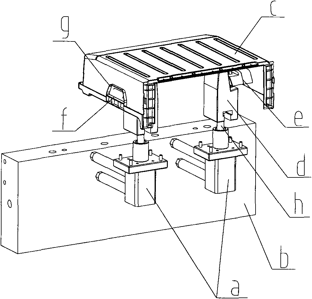
[0048] see figure 1 , the cylinder a is placed in the movable template b, one end of the passive slider e is the forming glue position g, and the other end is opened with a "T"-shaped groove, and the active slider d is fixed with a piston rod h that is fixed to the direction of movement of the piston rod h of the cylinder a. The "T" shaped block with an oblique angle, the "T" shaped block on the active slider d is slidingly matched with the "T" shaped groove on the passive slider e. At the same time, there is a "T"-shaped groove at the bottom of the active slider d, which is matched with the joint of the piston rod h of the oil cylinder a. During the core-pulling process, the oil cylinder a pulls the active slider d to move along the direction of the piston rod h, thereby driving The passive slider e moves toward the interior of the product c in a direction perpendicular to the moving direction of the piston rod h in the insert groove, so as to realize core pulling and forming...

Embodiment 2

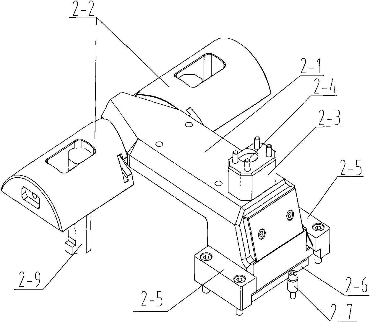
[0057] Different from the above-mentioned embodiments, the inclined slide between the active slider 2-1 and the passive slider 2-2 is slidably fitted into an inverted "L"-shaped block 2-10 and an oblique inverted "L"-shaped groove 2-11 The sliding fit, the inverted "L" shaped block 2-10 is inserted into the inclined inverted "L" shaped groove 2-11, that is, as Figure 7-1 and Figure 7-2 The shown "draw hook" structure ramp is matched.


PUM


Abstract

The invention provides an injection mould provided wtih a core-pulling mechanism driven by mould opening and closing actions, wherein, the injection mould can solve the problems that the core-pulling mechanism adopting a hydraulic cylinder to perform the core-pulling from the lower part of a product has the disadvantages of complicated structure, high cost and bad stability when the core-pulling is carried out in conventional core-pulling manners such as obliquely propping and the like so as to solve an internal inverted buckle existing in the product and so on. The injection mould adopts thetechnical scheme as follows: a driving slide block is connected with a mould movable template in a sliding manner, and the sliding direction is perpendicular to the mould opening direction of the mould; at least one side surface at the front end of the driving slide block takes the shape of a wedge; a driven slide block is inserted in an inserted block; in addition, the driven slide block is provided with a wedged end surface and matched with the driving slide block through an inclined slideway in a sliding manner. The core-pulling mechanism of the injection mould utilizes an inclined guide pillar to drive the slide block when the mould is opened and closed, the core-pulling action is completed in the direction perpendicular to the mould opening and closing direction, the problem of the internal inverted buckle can be solved, the strucutre is simple, the cost is low, the stability of the mould is good, and the injection moulding period is short.

Description

technical field [0001] The invention relates to the field of mold design, in particular to an improvement of a core-pulling mechanism in a mold. Background technique [0002] In terms of injection mold design, the inclined top mechanism is generally used to pull the core of the internal undercut of the general product. For some cases where the internal undercut of the injection molded product cannot be solved by conventional methods such as inclined top, the oil cylinder is generally used to pull the core from the bottom of the product. , in order to achieve the smooth release of plastic products. Schematic diagram of the cylinder core pulling mechanism, such as figure 1 shown. [0003] The disadvantages of using cylinder core pulling are as follows: [0004] 1. The structure is complex and takes up a lot of space. The oil cylinder core-pulling mechanism needs to open an opening for placing the oil cylinder on the formwork, which will have a certain impact on the strength...

Claims


Application Information

Patent Timeline
Patent Type & Authority Applications(China)
IPC IPC(8): B29C45/26
Inventor 赵西金王怀国王涛史宇辉
Owner QINGDAO HAIER MOLDS
Why Eureka
Try Eureka