Pinch roll type forced centering device

A technology of forced centering and pinch rollers, applied in transportation and packaging, coiling strips, thin material handling, etc., can solve problems affecting the quality of steel strips, improve product quality and yield, improve continuity, Avoid over-pickling effects

Inactive Publication Date: 2011-06-29
上海欧达电气成套设备工程有限公司 +1
View PDF0 Cites 3 Cited by
  • Summary
  • Abstract
  • Description
  • Claims
  • Application Information

AI Technical Summary

Problems solved by technology

[0007] The object of the present invention is to provide a pinch roller type forced centering device that not only enhances the deformation resistance of the steel belt, but also reduces the "reverse thrust" of the guide baffle on the steel belt, so as to solve the problem of the side guide centering device of the vertical roller. Excessive lateral force may easily cause "lotus leaves" or even "edge cracks" on the edge of the steel strip, which will affect the quality of the steel strip

Method used


Image

  • Pinch roll type forced centering device
  • Pinch roll type forced centering device
  • Pinch roll type forced centering device

Examples


Embodiment Construction

[0035] A preferred embodiment of the present invention is given below in conjunction with the accompanying drawings to describe the technical solution of the present invention in detail.

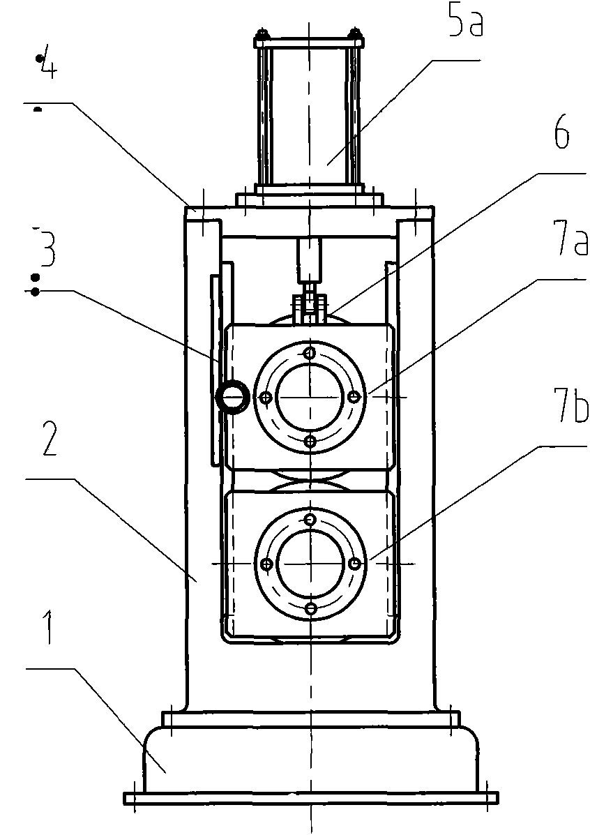
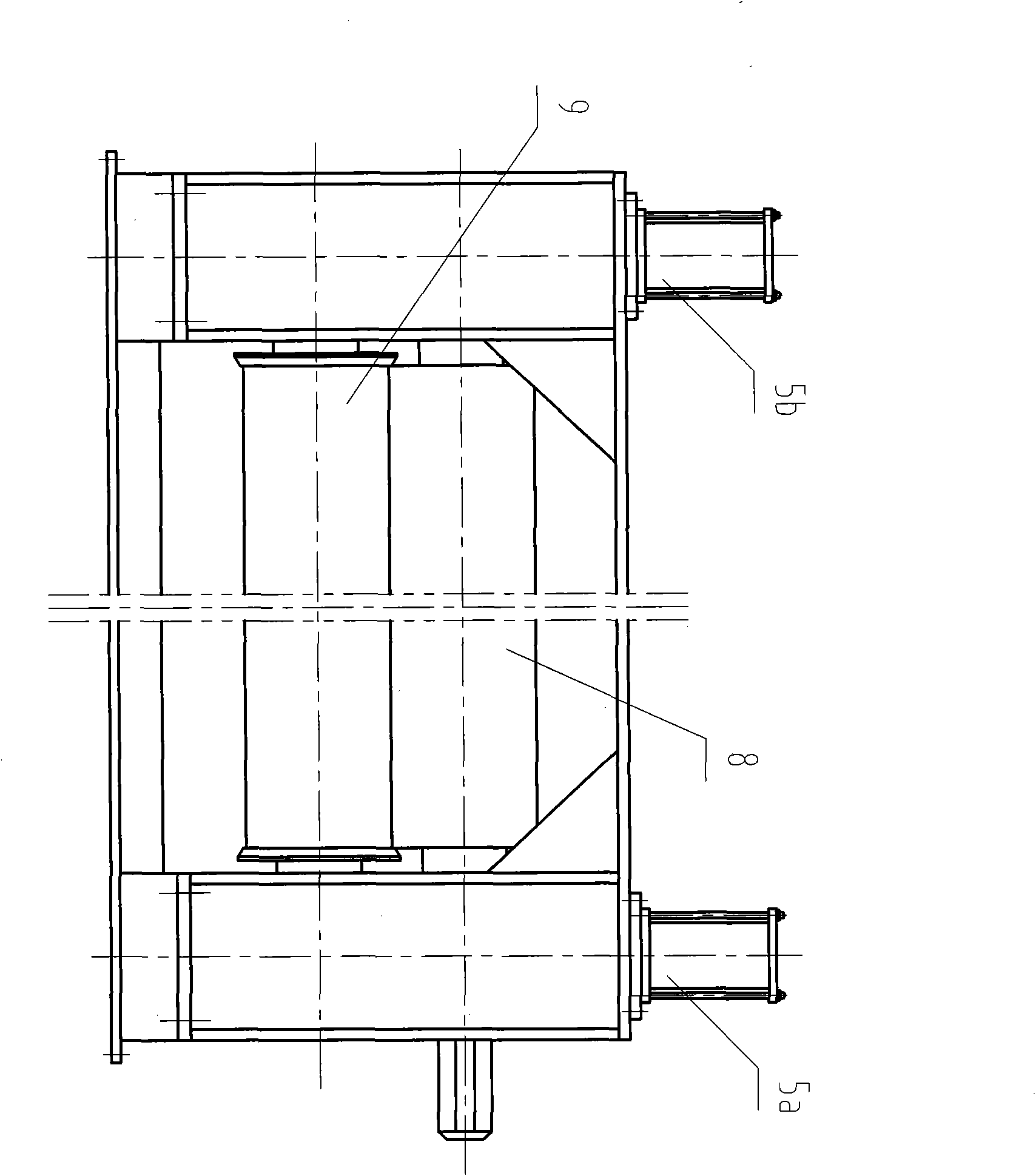
[0036] Such as Figure 1-3 As shown, the pinch roller type forced centering device consists of a base 1, an open frame 2 (lined sliding guide rail), an upper connecting fixed plate 4, a first lifting cylinder 5a and a second lifting cylinder 5b, and a synchronous rack and pinion 3 It is composed of upper and lower pinch type centering rollers (including upper roller 8 and lower roller 9). Wherein the upper roller 8 is a driving roller, and the lower roller 9 is a driven roller. The centered steel strip 13 is between the upper roll 8 and the lower roll 9 .

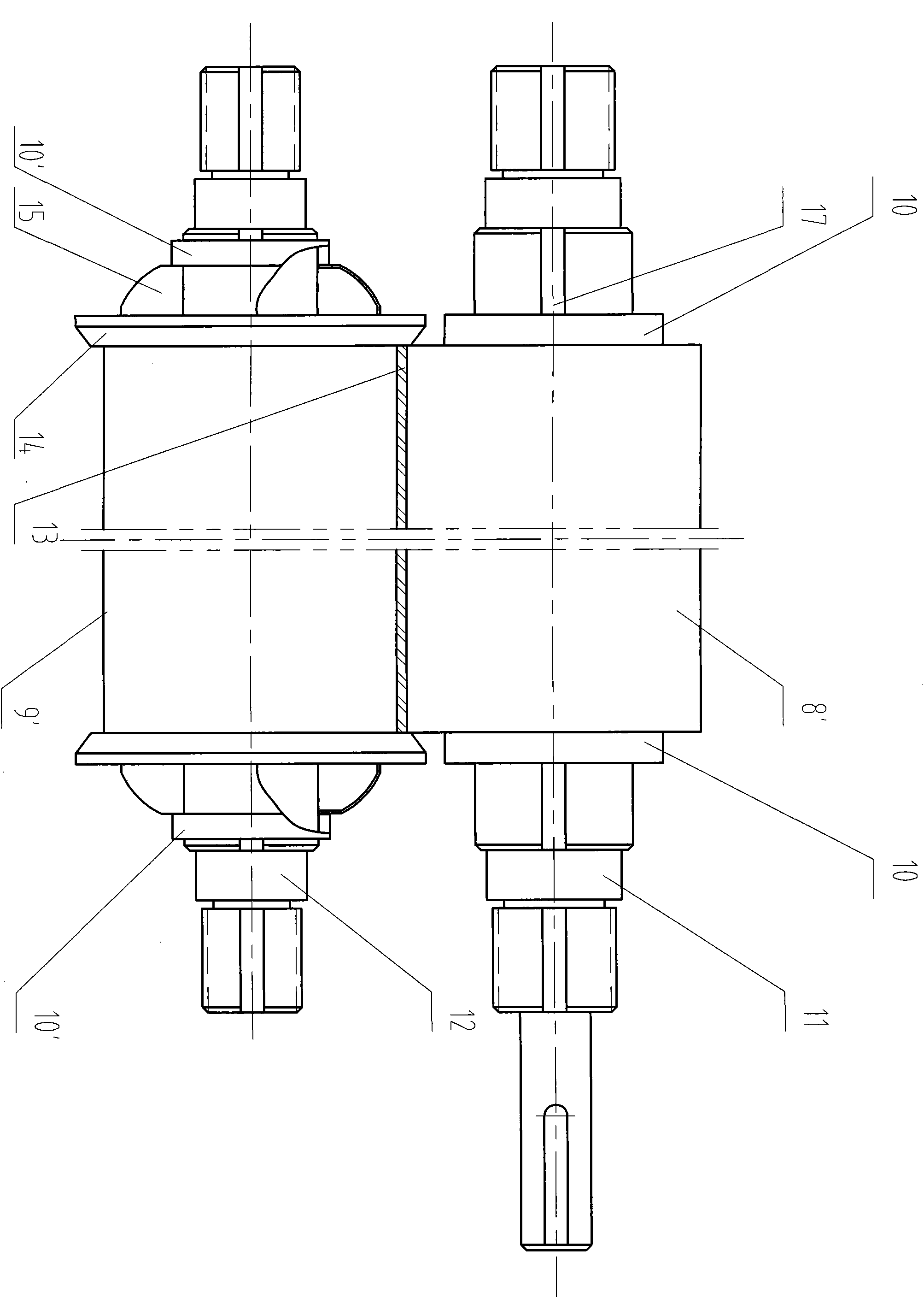
[0037] The upper roller 8 includes: the first upper roller bearing seat 7a and the second upper roller bearing seat (the second upper roller bearing seat has the same structure as the first upper roller bearing seat, corresponding to t...


PUM

PropertyMeasurementUnit
thicknessaaaaaaaaaa

Abstract

The invention provides a pinch roll type forced centering device, which comprises a centered steel strip, a base and an open rack of a lining sliding guide rail, wherein the upper part of the open rack is connected with an upper connecting fixed plate, an upper roll and a lower roll which are parallel up and down and have the same length as a drum are arranged in the open rack in the vertical direction, and a first lifting cylinder and a second lifting cylinder are fixedly arranged on the upper connecting fixed plate respectively; and two ends of the upper roll are connected with the first lifting cylinder and the second lifting cylinder respectively. The device greatly improves the deformation resistant strength of the steel strip, and simultaneously reduces 'reverse thrust' of a guide rail baffle plate on the steel strip.

Description

technical field [0001] The invention relates to a steel strip centering device in the metallurgical industry, in particular to a push-pull type pickling unit, the thickness of the centered steel strip is ≥0.5mm, and the pinch before the shearing edge of the disc under the condition of no tension or slight tension before and after Roller forced centering device. Background technique [0002] With the development of social economy and users' higher and higher requirements for product quality, metallurgical production enterprises must continuously improve equipment configuration and increase unit production capacity. Whether it is hot rolling or cold rolling, there is a higher requirement for the continuity of the production equipment in the whole process, and it is hoped that the processing capacity of the equipment in the process section will be increased as much as possible, which will inevitably increase the length of the unit. [0003] Therefore, it is particularly import...

Claims


Application Information

Patent Timeline
Patent Type & Authority Applications(China)
IPC IPC(8): B65H23/038C23G3/02
Inventor 陈广达艾小平
Owner 上海欧达电气成套设备工程有限公司
Why Eureka
Try Eureka