Industrial drying machine
A technology for industrial clothes dryers and cabinets, which is applied to household clothes dryers, washing devices, textiles and papermaking, etc., to achieve the effects of reducing use costs, improving heating efficiency, and reducing heat energy consumption
Inactive Publication Date: 2011-06-29
肖泽彬
View PDF5 Cites 26 Cited by
- Summary
- Abstract
- Description
- Claims
- Application Information
AI Technical Summary
Problems solved by technology
The air supply method of the air guiding device is changed from the traditional air supply from the radial direction to the inner cylinder, and changed to the air supply from the axial direction, which solves the problem of radial air supply shielding the air flow due to the high-speed rotation of the inner cylinder. Axial air supply, sufficient airflow and less heat loss, coupled with the high-speed rotating inner cylinder can shield the hot air introduced into the inner cylinder, so that the heat is not easy to lose, greatly improving the energy utilization rate
Method used
View moreImage
Smart ImageViewing Examples

Examples
Embodiment 1
Embodiment 2
Login to View More PUM
 Abstract
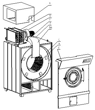
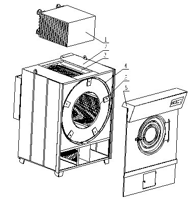
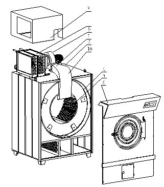
The invention belongs to the technical field of industrial washing machinery and in particular relates to an industrial drying machine. The machine comprises a case, a door body part, an external cylinder arranged inside the case, an internal cylinder installed in the external cylinder and an air heating device installed on the case. The machine also comprises a wind guide device, wherein one endof the wind guide device is connected with the air heating device and the other end of the wind guide device stretches into the internal cylinder along the axial direction of the internal cylinder; the air heating device comprises a steam radiating box and a heat collecting cover connected with the steam radiating box; and the steam radiating box comprises a radiating primary box and a radiating secondary box which are connected with each other. The wind supply mode of the wind guide device is changed from the traditional mode of supplying wind from the radial direction to the internal cylinder to the mode of supplying wind from the axial direction, thus solving the problem of airflow shielding due to high-speed rotation of the internal cylinder during radial wind supply. As the wind is supplied from the axial direction, the airflow is sufficient and the heat loss is low, thus greatly improving the energy utilization rate, and meanwhile, the two-stage air heating mode further effectively prevents the heat energy from losing, thus lowering the use cost of the drying machine.
Description
industrial clothes dryer technical field The invention belongs to the technical field of industrial washing machines, in particular to an industrial clothes dryer. Background technique Clothes dryers are a type of washing machinery and are generally used to remove moisture from clothing and other textiles after washing and dehydration. Most of the traditional clothes dryers are drum-type, and their working principle is to heat the surrounding air and transport it into the drum, where the hot air is used to evaporate water. Most clothes dryers include an inner cylinder and an outer cylinder. The inner cylinder is provided with an air inlet to circulate the working gas. The inner cylinder is driven by a belt to rotate, and the hot and humid air generated is discharged out of the cylinder, leaving dry air. Continue drying the laundry. As shown in Figure 1, the existing dryers inject hot air into the inner cylinder from the injection port 3 on the top of the dryer (that is, ...
Claims
Login to View More Application Information
Patent Timeline
 IPC IPC(8): D06F58/04D06F58/26
Inventor 肖泽斌
Owner 肖泽彬
Features
- Generate Ideas
- Intellectual Property
- Life Sciences
- Materials
- Tech Scout
- Unparalleled Data Quality
- Higher Quality Content
- 60% Fewer Hallucinations
Learn More Browse by: Latest US Patents, China's latest patents, Technical Efficacy Thesaurus, Application Domain, Technology Topic, Popular Technical Reports.
© 2025 PatSnap. All rights reserved.Legal|Privacy policy|Modern Slavery Act Transparency Statement|Sitemap|About US| Contact US: help@patsnap.com