Radiator fan frame

A cooling fan and frame technology, which is applied to the components of the pumping device for elastic fluid, non-variable-capacity pumps, machines/engines, etc., can solve problems such as poor structural strength, and reduce resonance and noise. , Best overall structural strength, reduce the effect of vibration transmission

Active Publication Date: 2011-06-29
SUNON ELECTRONICS KUNSHAN
View PDF2 Cites 2 Cited by
  • Summary
  • Abstract
  • Description
  • Claims
  • Application Information

AI Technical Summary

Problems solved by technology

[0005] The purpose of the present invention is to solve the disadvantages of poor structural strength in the prior art, to provide a non-circular barrier, which can reduce the overall structural strength compared with the prior art Vibration transmission to reduce resonance and noise cooling fan frame

Method used


Image

  • Radiator fan frame
  • Radiator fan frame
  • Radiator fan frame

Examples


Embodiment Construction

[0028] In order to make the above-mentioned and other objects, features and advantages of the present invention more comprehensible, the preferred embodiments of the present invention are specifically cited below, together with the accompanying drawings, as follows:

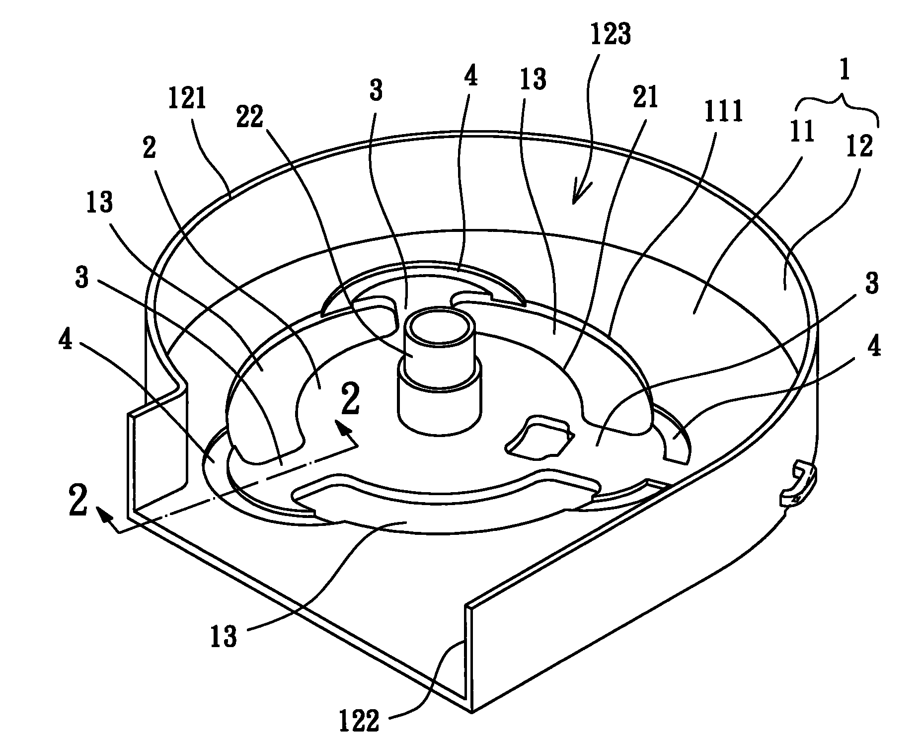
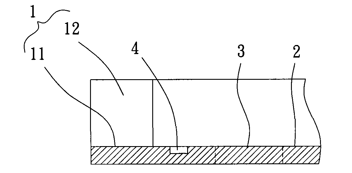
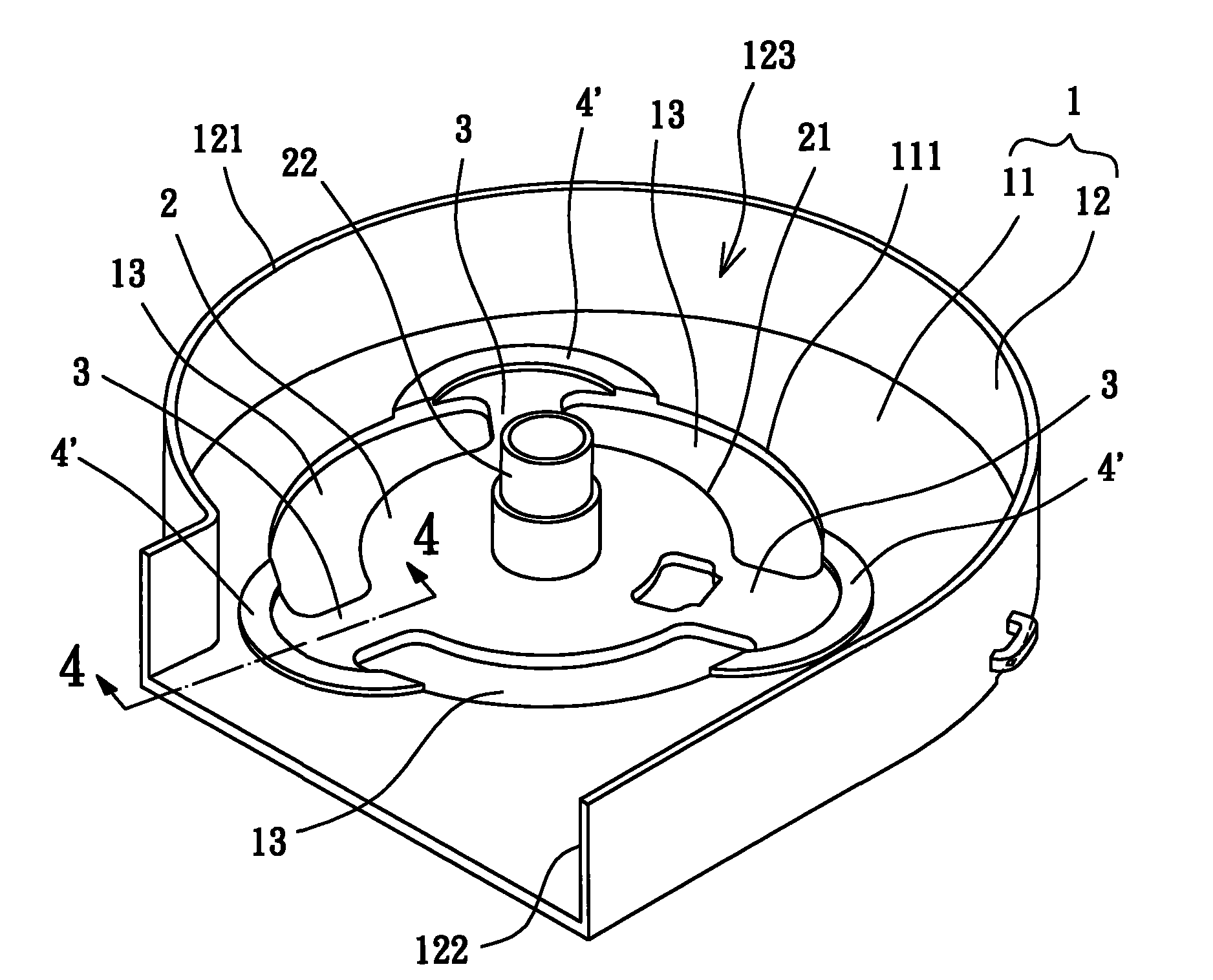
[0029] Please refer to figure 1 and 2 Shown is the cooling fan frame of the first embodiment of the present invention, the cooling fan frame includes a frame body 1 , a base 2 , several ribs 3 and several blocking parts 4 . The plurality of ribs 3 and the plurality of barriers 4 are arranged between the frame body 1 and the base 2, and the base 2 can be combined with components (not shown) such as fan motors and fan blades, so as to A cooling fan is formed.

[0030] The frame body 1 has a ring plate 11 and a side wall 12 . The ring plate 11 has an inner peripheral edge 111 and an outer peripheral edge, and the side wall 12 extends axially from the outer peripheral edge of the ring plate 11 . In addition, the ...


PUM


Abstract

A radiator fan frame comprises a frame body, a base, a plurality of fins and a plurality of obstructing parts. The frame body is provided with an annular plate and a side wall, the side wall is extended by the outer periphery of the annular plate in the axial direction, and the centre of the base is provided with a coupling part; one end of each fin is connected with the inner periphery of the annular plate, and the other end of each fin is connected with the outer periphery of the base; each obstructing part is arranged between the annular plate and the base. Therefore, the radiator fan frame can achieve the effect that the vibration transmission is reduced for lowering the resonance and noise under the premise that the radiator fan frame is kept at a better structural strength.

Description

technical field [0001] The invention relates to a heat dissipation fan frame, in particular to a heat dissipation fan frame which can reduce vibration transmission and reduce noise. Background technique [0002] Existing heat dissipation fan frame, as shown in the Patent No. 200829142 "Base Design of Heat Dissipation Structure" in Taiwan, China, includes a base, and a shaft tube is arranged in the center of the base, and the shaft tube can support a fan wheel to rotate. A groove is also provided, and the groove is located outside the outer diameter of the shaft tube. [0003] The groove of the existing structure is annularly arranged outside the outer diameter of the shaft tube to reduce the transmission of vibration generated when the fan wheel rotates to the outside of the base, thereby reducing resonance and noise. [0004] However, the ring-shaped groove also causes the thickness of the base around the shaft tube to become thinner, resulting in insufficient support stre...

Claims


Application Information

Patent Timeline
Patent Type & Authority Applications(China)
IPC IPC(8): F04D29/52F04D29/66
Inventor 洪银树卢加达
Owner SUNON ELECTRONICS KUNSHAN
Why Eureka
Try Eureka