
Automatic control circuit

An automatic control circuit and control circuit technology, applied in general control systems, control/regulation systems, instruments, etc., can solve the problems of simple structure automatic control circuits, traditional electrical appliances do not have automatic control, etc., and achieve low cost and wide application. , to meet the needs of automatic control

Inactive Publication Date: 2012-07-04
韩俊
View PDF0 Cites 0 Cited by
  • Summary
  • Abstract
  • Description
  • Claims
  • Application Information

AI Technical Summary

Problems solved by technology

[0002] Now, most smart electrical appliances with single-chip or digital circuits have realized automatic control and protection, but there are still a large number of traditional electrical appliances that do not have automatic control or use their own unique circuits to achieve individual control
At present, there is no simple structure, low cost and widely applicable automatic control circuit for traditional electrical appliances or such automatic control circuit is disclosed

Method used


Image

  • Automatic control circuit
  • Automatic control circuit
  • Automatic control circuit

Examples


Embodiment Construction

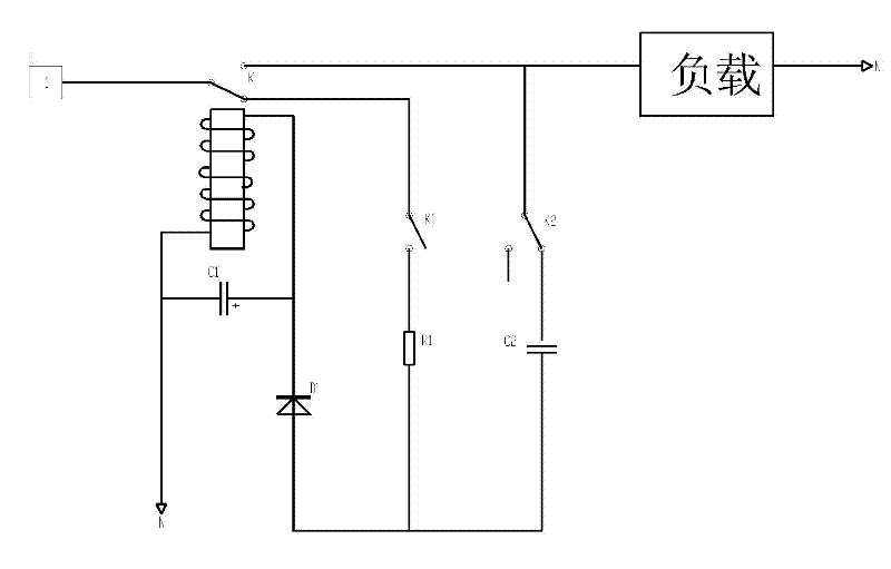
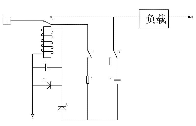
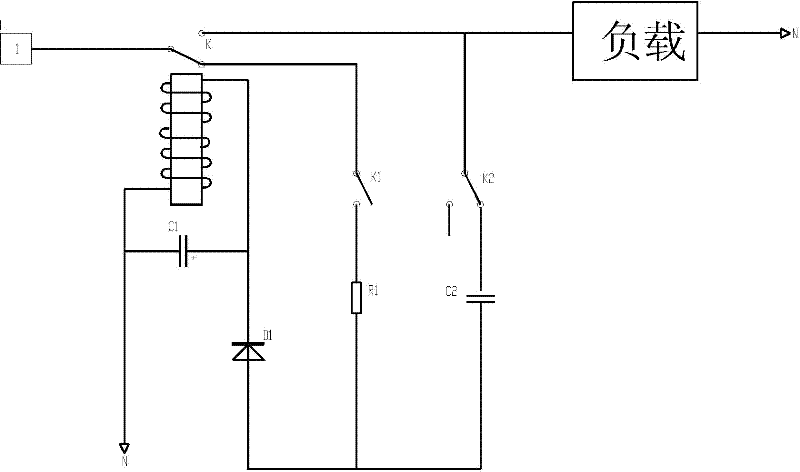
[0016] Such as figure 1 As shown, the automatic control circuit of Embodiment 1 of the present invention includes an input terminal electrically connected to the live wire L of the AC power supply, an output terminal electrically connected to the load, and the other output terminal electrically connected to the start switch K1 of the single-pole double-throw relay control switch K; One end of the relay coil in the relay control switch K is connected to the ground wire N of the AC power supply, and the other end is electrically connected to the other output end of the control switch K through the first diode D1, the first resistor R1, and the start switch K1 in turn, or An output end of the control switch K is electrically connected through the first diode D1, the second capacitor C2, and the normally closed detection switch K2 in sequence; the control circuit also includes a first capacitor C1 connected in parallel with the coil. Its working principle is as follows: when start...


PUM


Abstract

The invention relates to an automatic control circuit. The automatic control circuit comprises a relay control switch (K) with an input end electrically connected with an alternating current power supply fire wire (L) and an output end electrically connected with a load, wherein one end of a relay coil in the relay control switch (K) is connected with an alternating current power supply earth wire (N) and the other end of the relay coil is electrically connected with a fire wire (L) via a first diode (D1) and a starting switch (K1) in sequence or is electrically connected with the output end of the control switch (K) via the first diode (D1) and a normally closed detection switch (K2) in sequence; and the control switch also comprises a first capacitor (C1) connected with the coil in parallel. The automatic control circuit has simple structure and low cost, is combined with various detection switches, has wide application range and greatly meets the automatic control requirements of old electrical appliance improvement or the traditional electrical appliances.

Description

technical field [0001] The invention relates to electronic circuits, in particular to an automatic control circuit. Background technique [0002] Now, most smart appliances with single-chip or digital circuits have realized automatic control and protection, but there are still a large number of traditional appliances that do not have automatic control or use their own unique circuits to achieve individual control. At present, there is no automatic control circuit with simple structure, low cost and wide applicability for conventional electrical appliances or such an automatic control circuit has been disclosed. Contents of the invention [0003] The technical problem to be solved by the present invention is how to provide an automatic control circuit with simple structure, low cost and wide application. [0004] The technical problem of the present invention is solved in this way: build an automatic control circuit, including the control switch whose input end is electric...

Claims


Application Information

Patent Timeline
Patent Type & Authority Patents(China)
IPC IPC(8): G05B9/02
Inventor 韩俊
Owner 韩俊
Learn More