Temperature measurement charging method of storage battery

A charging method and storage battery technology, applied in secondary battery charging/discharging, battery circuit devices, secondary battery repair/maintenance, etc., can solve problems such as charging dehydration, and achieve easy dehydration, reliability and service life Guarantee and ensure the effect of service life

Active Publication Date: 2013-02-27
JIANGSU MINGAN ELECTRIC +1
View PDF2 Cites 0 Cited by
  • Summary
  • Abstract
  • Description
  • Claims
  • Application Information

AI Technical Summary

Problems solved by technology

[0007] How to solve the problem of dehydration during charging at low temperature is a technical problem in this field

Method used


Image

  • Temperature measurement charging method of storage battery
  • Temperature measurement charging method of storage battery
  • Temperature measurement charging method of storage battery

Examples


Embodiment 1)

[0029] The temperature measurement and charging method of the storage battery in this embodiment includes:

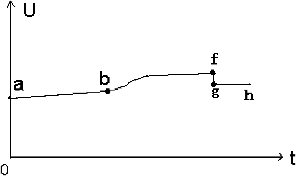
[0030] A: At the initial stage of charging, if the temperature of the electrolyte in the battery is not lower than 25°C, charge the battery with a constant current, and the charging current is 0.1C; until the voltage of the battery reaches the gassing voltage of the battery , carry out constant voltage charging; when the voltage of the battery reaches the rated saturation voltage, it will be charged after a period of floating charging; the period of time is 1-24 hours, and the current of floating charging is 0.01-0.02c; During the charging and charging process, when the temperature of the electrolyte is measured to rise, the float charging is stopped immediately to prevent the battery from overheating. Because the floating charging current is small, the floating charging voltage is generally below the gassing point voltage of the battery.

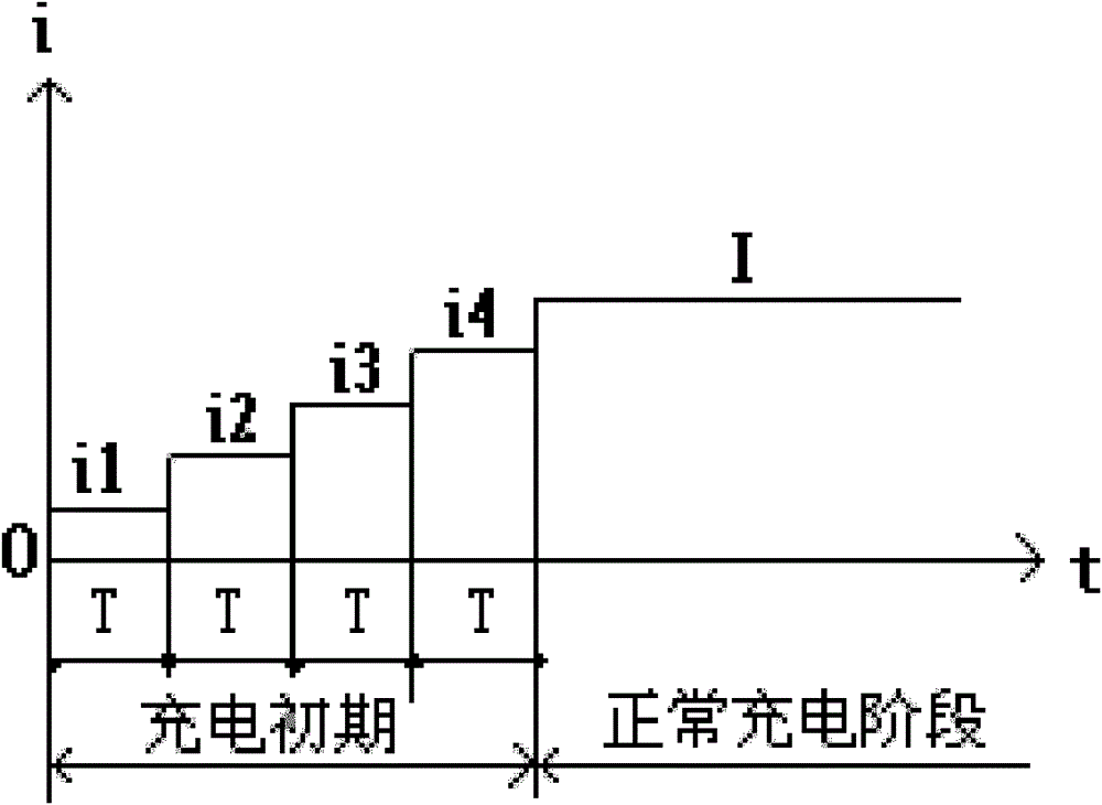
[0031] B: At the initial sta...

Embodiment 2)

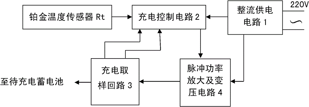
[0044] See Figure 3-5 , the charging device using the temperature measurement and charging method of the above storage battery, comprising: a rectification power supply circuit 1, a pulse power amplification and voltage transformation circuit 4 connected to the power supply output end of the rectification power supply circuit 1 for providing charging power to the storage battery, The charging sampling circuit 3 for detecting charging current and voltage, the platinum temperature sensor Rt installed in the electrolyte of the storage battery, and the feedback signal used to control the pulse power amplification and voltage transformation circuit 4 in real time through the charging sampling circuit The charging control circuit 2 of the output voltage; the charging control circuit 2 is suitable for the actual temperature of the battery electrolyte measured by the platinum temperature sensor, and the corresponding charging procedure in the first embodiment is adopted.

[0045] The...


PUM


Abstract

The invention relates to a temperature measurement charging method of a storage battery, which is used for preventing water loss during charging at a low temperature, wherein the method provided by the invention comprises the following steps: A, implementing constant-current charge when the temperature for the electrolyte of a storage battery is not less than 25 DEG C in the primary charging stage, sequentially implementing constant-current charge and floating charge when the voltage of the storage battery is lived up to gassing voltage value of the storage battery; B, charging the storage battery for one or more of sections with a charging current of less than 0.1 C when the temperature of the electrolyte is less than 25 DEG C in the primary charging stage, wherein the charging currents of the sections are increased in turn when the storage battery is charged for the plurality of sections with the charging current of less than 0.1 C, the constant-current charge with the charging current of 0.1 C is used until the temperature of the electrolyte is not less than 25 DEG C, and the constant-current charge and floating charge are sequentially implemented until the voltage of the storage battery reaches the assign voltage value of the storage battery.

Description

technical field [0001] The invention relates to the technical field of accumulator charging, in particular to a temperature measuring and charging method for a valve-regulated lead-acid accumulator. Background technique [0002] A lead-acid battery is composed of multiple cells connected in series. The two most important factors for the premature end of life of valve-regulated lead-acid batteries are softening corrosion of the positive grid and excessive loss of water from the electrolyte. For the maintenance-free valve-regulated lead-acid battery, the capacity will be reduced by 20% if the water loss is 10%, and the life will be terminated if the water loss is 25%. Therefore, how to reduce the water loss during the charging process of this type of battery has become the key to prolonging the life of the valve-regulated lead-acid battery. [0003] The main form of dehydration of valve-regulated lead-acid batteries is that when the charging voltage rises to a single cell vo...

Claims


Application Information

Patent Timeline
Patent Type & Authority Patents(China)
IPC IPC(8): H01M10/44H02J7/00
CPCY02E60/12Y02E60/10
Inventor 杨龙兴
Owner JIANGSU MINGAN ELECTRIC
Why Eureka
Try Eureka