Supercharge Your Innovation With Domain-Expert AI Agents!

Scroll fluid machine

A fluid machinery and scroll technology, applied in the direction of rotary piston machinery, mechanical equipment, rotary piston pumps, etc., can solve the problems of rising manufacturing costs, pressure pulsation, and reduced reliability, and achieve manufacturing cost reduction and volumetric efficiency The effect of improving and reducing the amount of leakage

Inactive Publication Date: 2011-06-29
RICHSTONE
View PDF8 Cites 1 Cited by
  • Summary
  • Abstract
  • Description
  • Claims
  • Application Information

AI Technical Summary

Problems solved by technology

[0004] However, in the scroll type fluid machine described in Japanese Patent Application Laid-Open No. 8-210269, since it is necessary to provide an anti-rotation mechanism for preventing the rotation of the rotary shaft and the orbiting scroll, the structure becomes complicated, and the manufacturing cost increases while being reliable. decreased sex
In addition, during one rotation of the drive shaft, the suction and discharge are performed only once, so the pressure pulsation increases, and the vibration and noise also increase.
[0005] In addition, in the scroll fluid machine shown in Japanese Patent No. 4014583, since an anti-rotation mechanism such as a driven crank mechanism is additionally provided in addition to the expander unit and the pump unit, the structure becomes complicated. At the same time, since it can only be set vertically, it cannot be set freely
And, since there is only one pump chamber, pressure pulsation caused by volume change occurs
Also, since there is a concern that the liquid refrigerant is partially vaporized by the heat of the generator, the pump cannot perform its inherent function.

Method used


Image

  • Scroll fluid machine
  • Scroll fluid machine
  • Scroll fluid machine

Examples


no. 1 approach

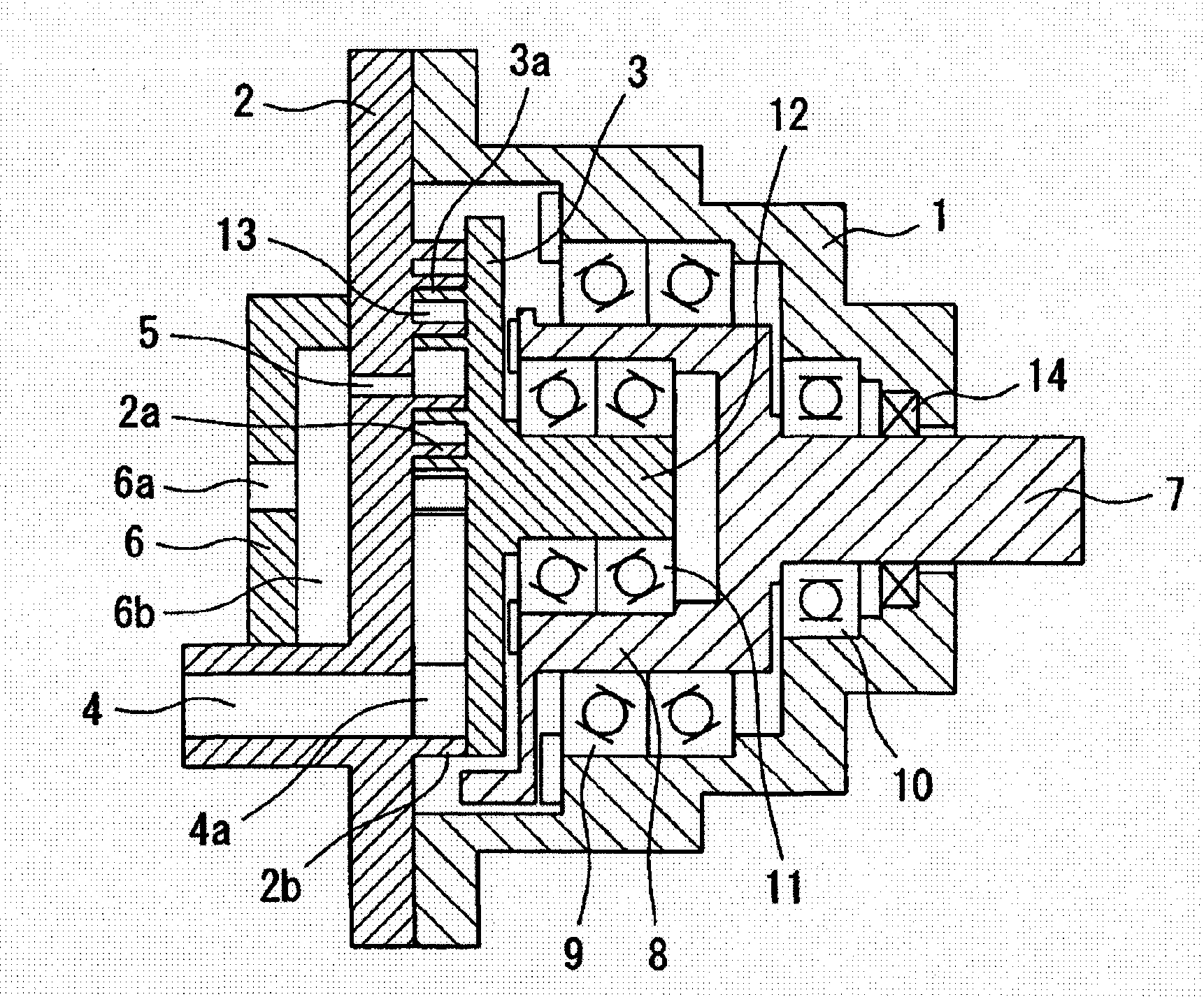
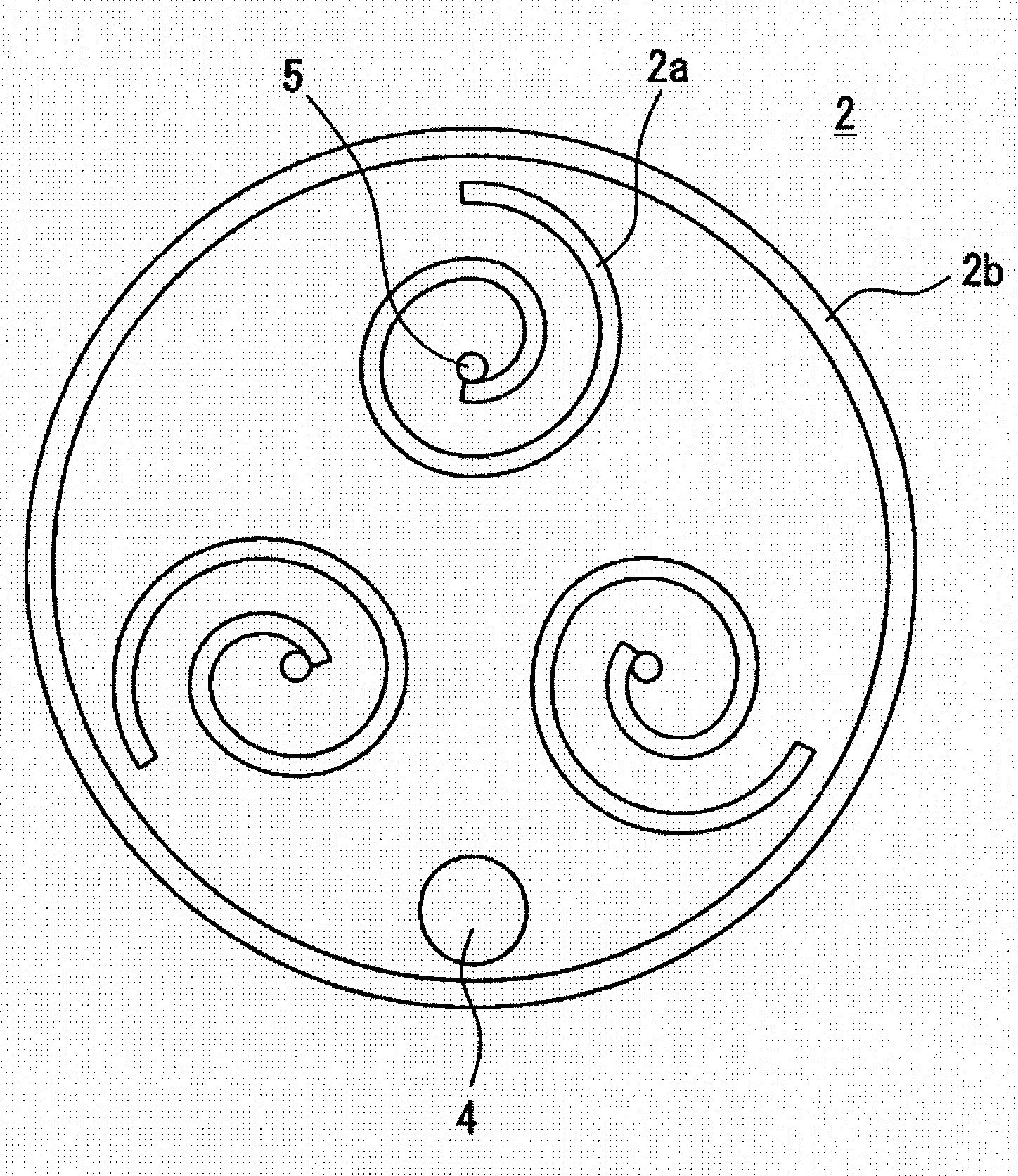
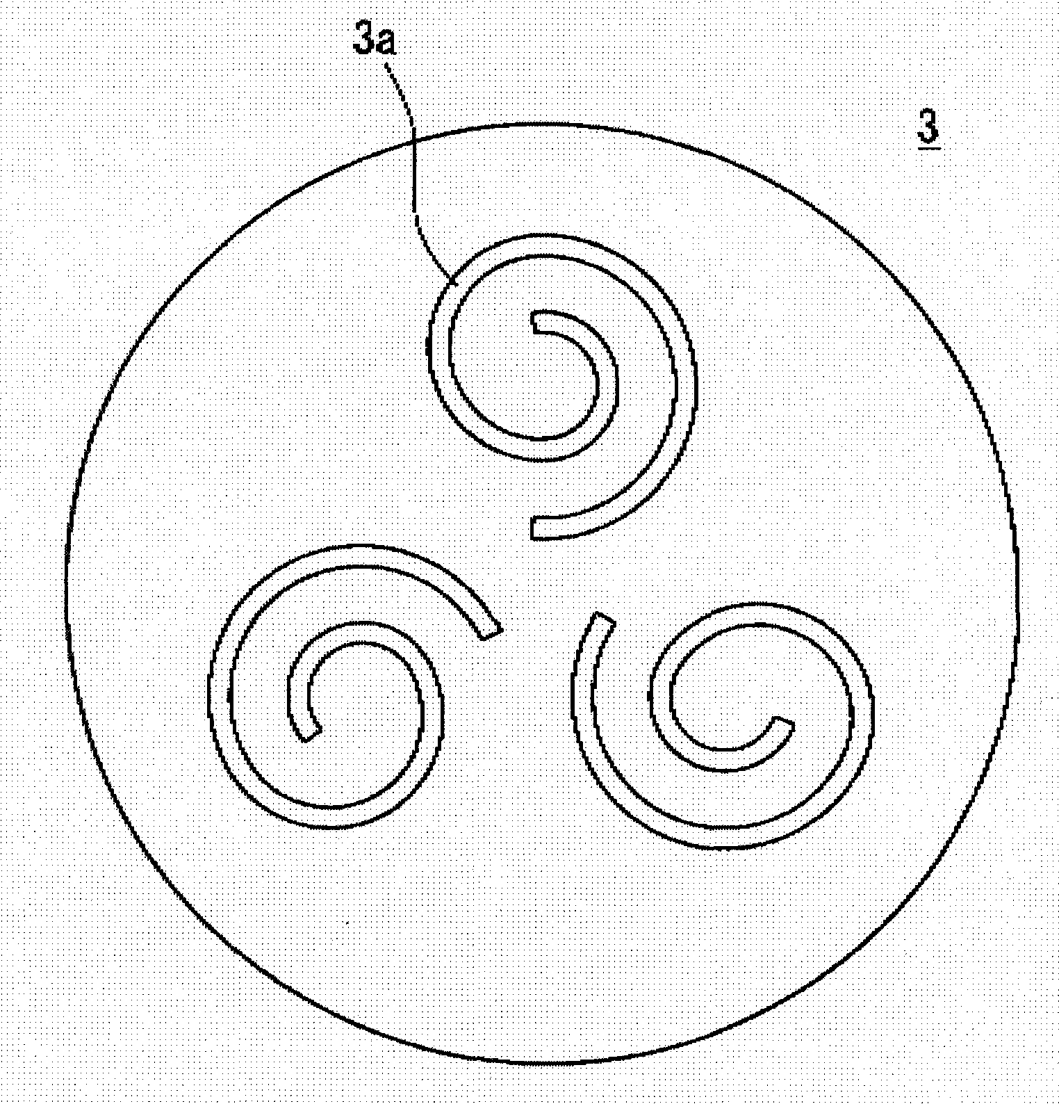
[0055] figure 1 It is a figure which shows the scroll type fluid machine of this invention; figure 2 yes means figure 1 A diagram of the fixed scroll of the scroll fluid machine shown; image 3 yes means figure 1 A diagram of the orbiting scroll of the scroll fluid machine shown. Such as figure 1 As shown, a fixed scroll 2 is installed on the casing 1, and three fixed flanges 2a are installed on the fixed scroll 2. The angular interval between adjacent fixed flanges 2a is 120 degrees, and the mutual phases are staggered by 120 degrees. A sealing wall 2b is provided on the outer periphery of the fixed scroll 2, a suction port 4 is provided on the fixed scroll 2, and a discharge port 5 is provided on the center of the fixed flange 2a of the fixed scroll 2. In addition, the rotating shaft 7 and the eccentric bushing 8 are integrally formed, the rotating shaft 7 and the eccentric bushing 8 are rotatably supported on the housing 1 via the main bearing 9 and the sub bearing 10...

no. 2 approach

[0062] Figure 5 It is a figure which shows another scroll type fluid machine of this invention. As shown in the figure, the cover 6 is fixed on the casing 1, and the fixed scroll 2 is installed on the cover 6 in a manner that can move upward along the axial direction of the rotary shaft 12, between the cover 6 and the fixed scroll 2 A discharge chamber gasket 6c is provided, and the fixed scroll 2 is prevented from rotating relative to the cover 6 by a pin 15 .

[0063] This scroll fluid machine and figure 1 Similarly, the scroll fluid machine shown does not need to provide an anti-rotation mechanism to prevent the rotary shaft 12 and the orbiting scroll 3 from rotating, so the structure becomes simple, the manufacturing cost is reduced, and the reliability is improved. And, since the fixed scroll 2 is pressed to the Figure 5 On the right side of the paper, the front end of the fixed flange 2a is in close contact with the orbiting scroll 3, and the front end of the orbiti...

no. 3 approach

[0065] Image 6 It is a figure which shows another scroll type fluid machine of this invention. As shown in the figure, the stator 20 is fixed on the casing 1, and the rotating shaft 24 is rotatably supported on the casing 1 via the first and second rotating bearings 22a, 22b. The rotor 21 is mounted on the rotating shaft 24, and the machine The housing 1, the stator 20, the rotating shaft 24, the rotor 21, and the like constitute the structure of the motor. In addition, the rotary shaft 25 (rotary member) is rotatably supported in the eccentric hole of the rotary shaft 24 via the first and second eccentric bearings 23a, 23b, and the center line of the rotary shaft 24 and the center line of the rotary shaft 25 deviate. That is, the rotary shaft 25 and the rotary shaft 24 are eccentrically and rotatably supported. Then, the orbiting flanges of the orbiting scroll 3 are attached to the rotary shaft 25 by bolts or the like in a state where relative rotation is prevented at the ...


PUM


Abstract

A stationary scroll lathe (2) is attached to a casing (1). The stationary scroll lathe (2) is equipped with three stationary laps (2a). An eccentric bush (8) is rotatably supported in the casing (1). A revolving shaft (12) is eccentrically supported in the eccentric hole of the eccentric bush (8). The revolving shaft (12) is integrally equipped with a scroll disc (3) having three revolving laps (3a). A plurality of pump chambers (13) are formed between the stationary laps (2a) and the revolving laps (3a). A suction port (4) is formed to communicate with a suction chamber formed in a seal wall (2b) of the outer circumference of the stationary scroll lathe (2). A discharge port (5) is formed in the stationary scroll lathe (2). While the eccentric bush (8) is making one revolution, a working fluid is sucked and discharged three times to and from the pump chambers (13). As a result, it is possible to realize a scroll fluid machine which can reduce pulsations, vibrations and noises and which has a small number of parts and a high reliability.

Description

technical field [0001] The present invention relates to a scroll type fluid machine used as a pump etc., for example, a scroll type fluid machine used alone as a liquid pump for pressure-feeding liquid refrigerant, working oil, etc. or combined with an expander, air compressor, vacuum pump, refrigerant A scroll fluid machine that uses a combination of a gas compressor and a compressor for an oxygen absorber to function as a pump. Background technique [0002] Conventional scroll fluid machines are shown in Japanese Patent Laid-Open No. 8-210269. In a scroll fluid machine used as a pump, the pump is formed by a pair of fixed scroll and orbiting scroll, and it is necessary to install Anti-rotation mechanisms such as driven cranks and crosshead rings. [0003] In addition, conventional scroll fluid machines, as shown in Japanese Patent No. 4014583, require an anti-rotation mechanism such as a driven crank and an Oldham ring in a scroll fluid machine in which a pump and an expa...

Claims


Application Information

Patent Timeline
Patent Type & Authority Applications(China)
IPC IPC(8): F04C18/02F01C1/02
CPCF04C23/001F04C18/0269F04C23/008
Inventor 黄富石黄光宣
Owner RICHSTONE
Features
  • R&D
  • Intellectual Property
  • Life Sciences
  • Materials
  • Tech Scout
  • Unparalleled Data Quality
  • Higher Quality Content
  • 60% Fewer Hallucinations
Learn More