Heat transfer tube for heat exchanger, heat exchanger, refrigerating cycle apparatus, and air conditioning apparatus
A heat exchanger and circulation device technology, applied in the field of heat transfer tubes, can solve the problems of reduced heat transfer performance in the tube and increased pressure loss in the tube, and achieve the effects of improving adhesion, suppressing rebound, and improving heat transfer performance
- Summary
- Abstract
- Description
- Claims
- Application Information
AI Technical Summary
Problems solved by technology
Method used
Image

Examples
Embodiment approach 1
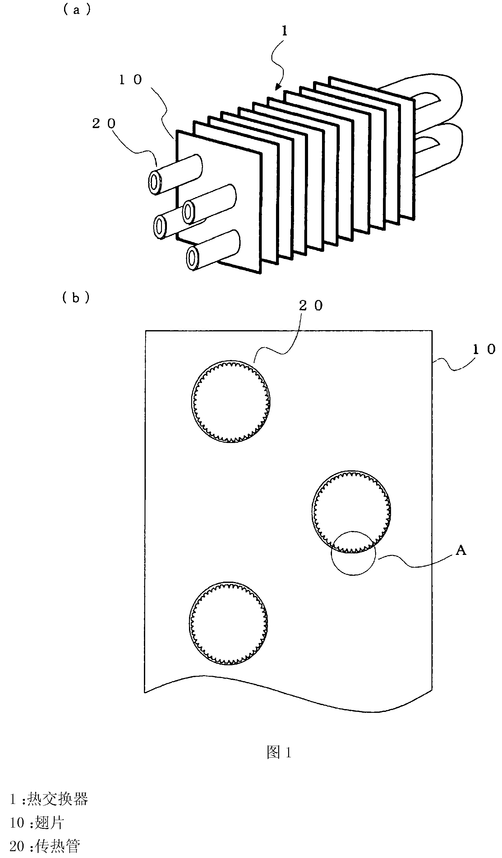
[0021] figure 1 It is a figure which shows the heat exchanger 1 which concerns on Embodiment 1 of this invention. figure 1 Among them, the heat exchanger 1 is a fin-and-tube heat exchanger widely used as an evaporator and a condenser of a refrigeration device, an air conditioner, and the like. figure 1 (a) shows a perspective view when the heat exchanger 1 is cut in the vertical direction, figure 1 (b) shows a part of the section.
[0022] The heat exchanger 1 is composed of a plurality of heat exchanger fins 10 and heat transfer tubes 20 . The heat transfer tubes 20 are provided so as to pass through the through-holes provided in the fins 10 with respect to the plurality of fins 10 arranged at predetermined intervals. The heat transfer tube 20 is a part of the refrigerant circuit of the refrigeration cycle apparatus, and the refrigerant flows through the inside of the tube. By transferring the heat of the refrigerant flowing inside the heat transfer tube 20 and the air fl...
Embodiment approach 2
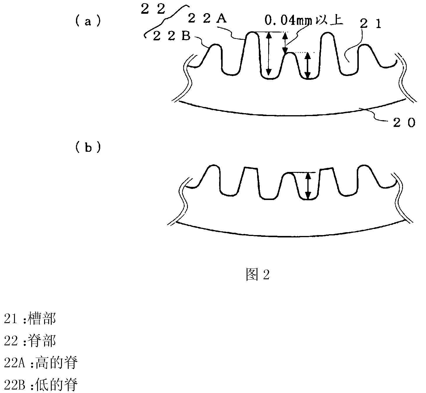
[0030] Figure 5 It is a figure which shows the shape of the tube inner surface of the heat transfer tube 20 of Embodiment 2. The configuration of the heat exchanger 1 is the same as that of the first embodiment. exist Figure 5 In , the same reference numerals are assigned to the parts that realize the same or equivalent functions as those in Embodiment 1 (the same applies to the following embodiments). In this embodiment, the difference H between the groove portion 21 and the ridge portion 22 after pipe expansion will be described.
[0031] Figure 6 It is a graph showing the relationship between the difference between the groove portion 21 and the ridge portion 22 after pipe expansion and the heat exchange rate. In the heat transfer tube 20, the larger the difference H between the groove portion 21 and the ridge portion 22 after tube expansion, the larger the surface area inside the tube, etc., and the higher the heat transfer rate. However, when the difference H betwe...
Embodiment approach 3
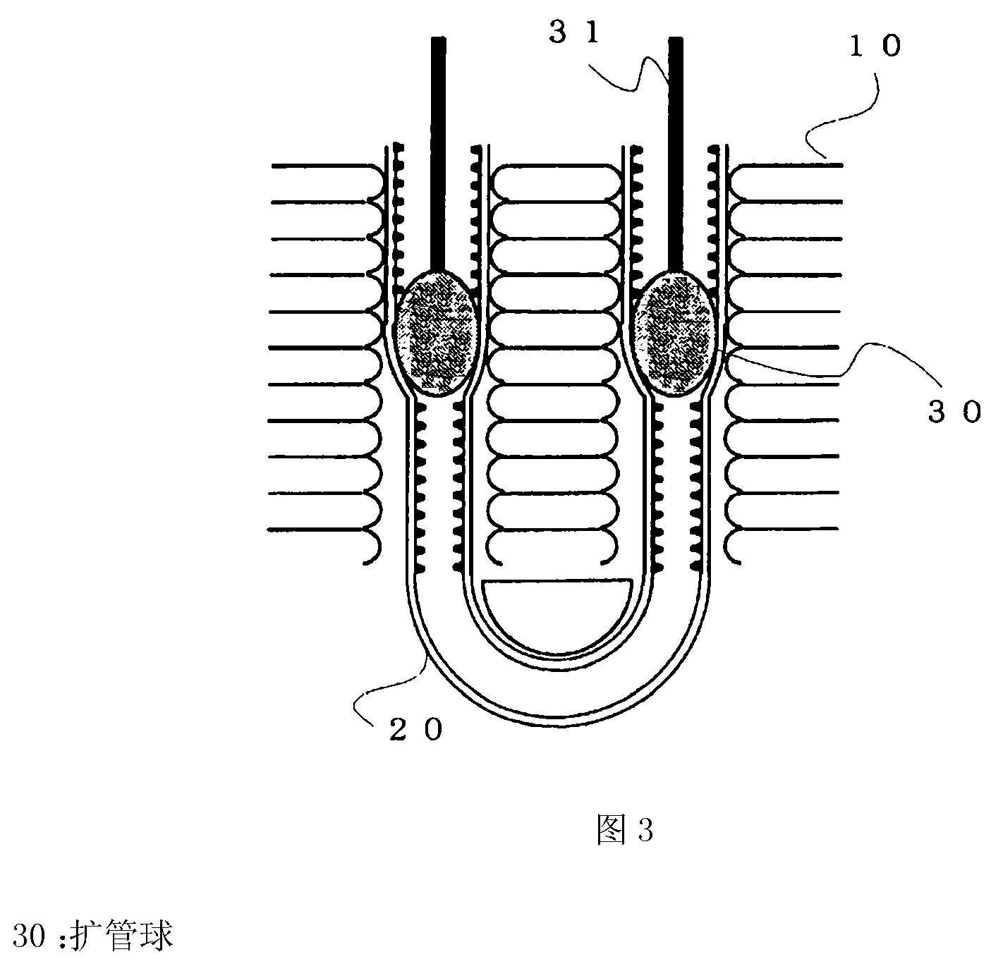
[0034] Figure 7 It is a figure which shows the shape of the tube inner surface of the heat transfer tube 20 of Embodiment 3. In Embodiment 3, in the heat exchanger 1 after tube expansion, the front end width W1 of the ridge top portion of the high ridge 22A is set to 0.035 to 0.05 mm, and the front end width W2 of the low ridge 22B is set to 0.035 mm to 0.05 mm. It is in the range of 0.03 to 0.035mm.
[0035] Regarding the tip width W1 of the high ridge 22A, when the tip width W1 after tube expansion is 0.035 mm or less, the top of the ridge is crushed when the tube is expanded using the tube expansion ball 30 , and the pressure generated by insertion is weakened. Therefore, expansion of the heat transfer tubes 20 is insufficient, the adhesion between the heat transfer tubes 20 and the fins 10 deteriorates, and the heat exchange rate significantly decreases. In addition, when the front end width W1 is set to be 0.05 mm or more, the cross-sectional area of the groove portion...
PUM
 Abstract
Description
Claims
Application Information
 - R&D
- Intellectual Property
- Life Sciences
- Materials
- Tech Scout
- Unparalleled Data Quality
- Higher Quality Content
- 60% Fewer Hallucinations
Browse by: Latest US Patents, China's latest patents, Technical Efficacy Thesaurus, Application Domain, Technology Topic, Popular Technical Reports.
© 2025 PatSnap. All rights reserved.Legal|Privacy policy|Modern Slavery Act Transparency Statement|Sitemap|About US| Contact US: help@patsnap.com