Phased array antenna and method of operating phased array antenna

A phased array antenna and antenna unit technology, which is applied to antennas, antenna components, diversity/multi-antenna systems, etc., can solve the problems of expensive construction and installation of phased array antennas

Active Publication Date: 2011-06-29
HANWHA PHASOR LTD
View PDF4 Cites 16 Cited by
  • Summary
  • Abstract
  • Description
  • Claims
  • Application Information

AI Technical Summary

Problems solved by technology

However, phased array antennas are generally more expensive to construct and install due to the precision required during manufacture to provide a reliable antenna array

Method used


Image

  • Phased array antenna and method of operating phased array antenna
  • Phased array antenna and method of operating phased array antenna
  • Phased array antenna and method of operating phased array antenna

Examples


Embodiment Construction

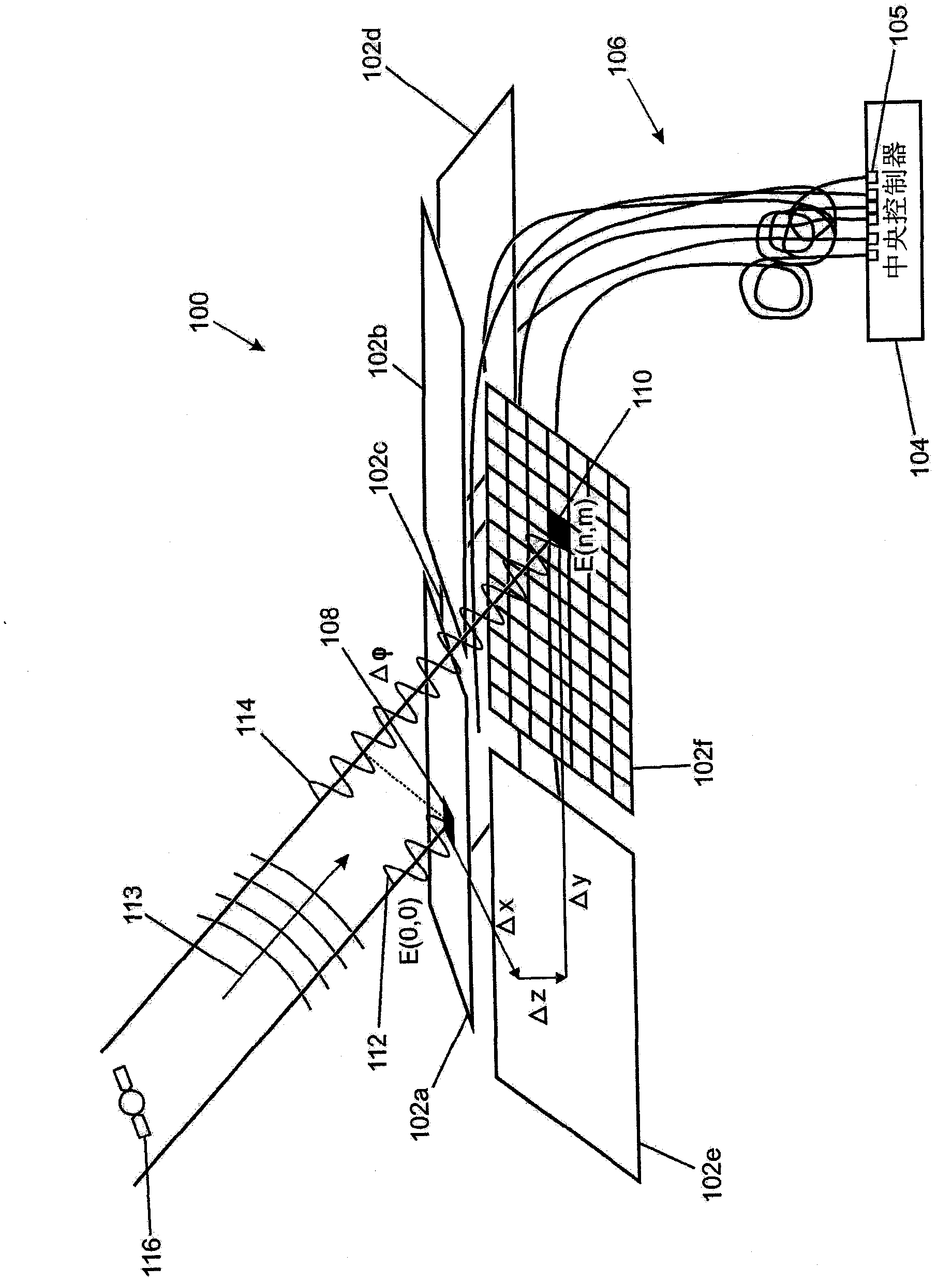
[0058] One or more embodiments of the present invention relate to phased array antennas, and in particular phased array antenna systems / boards that can be used to provide improved gain and signal-to-noise ratio when transmitting and receiving electromagnetic communication signals. The phased array antenna system may include one or more phased array antenna panels that automatically focus their maximum gain beams to transmitters or receivers of electromagnetic communication signals such as satellites .

[0059] Focusing the phased array antenna system reduces the bandwidth of the phased array antenna as a receiver. The noise experienced by the receiver is directly proportional to the bandwidth of the system. For example, if the bandwidth is reduced by a factor of 10, the signal-to-noise ratio improves by 10dB.

[0060] The bandwidth of an antenna system can be viewed as the frequency range over which antenna characteristics (such as beamwidth, input impedance, pattern, polari...


PUM


Abstract

An element of a phased array antenna is provided. The element comprises a phase tracking circuit configured to multiply the in-phase component (In) of a local output signal by the quadrature phase component (Qout) of an external output signal to generate a phase control signal (535) and / or to multiply the quadrature component (Qn) of a local output signal by the in-phase component (Iout) of an external output signal to generate a phase control signal (535).

Description

technical field [0001] The present invention relates to a phased array antenna and a method for operating a phased array antenna, in particular but not exclusively to a phased array antenna system / board for use in telecommunication systems. Background technique [0002] Reflector antennas such as satellite dishes are used in telecommunications systems and are simple and well understood. Reflector antennas form the majority of high gain antenna systems. In order to steer a reflector antenna, mechanical movement of the entire reflector is usually required, although alternatives such as moving the feed mechanically or electronically are also known. [0003] The speed at which a reflector antenna can steer the beam is limited by the mechanical limitations of the mass of the accelerating reflector or other movable part of the antenna. The mechanical precision of the moving mechanism also limits the positioning precision of the antenna beam. Also, any inaccuracies in the struct...

Claims


Application Information

Patent Timeline
IPC IPC(8): H01Q1/32H01Q3/26H04B7/08
CPCH01Q1/3216H01Q3/2605H01Q1/3275H04B7/0848H01Q3/267H04L27/2273H01Q1/32H01Q3/26H04B7/08H01Q3/34
Inventor R·梅奥
Owner HANWHA PHASOR LTD
Why Eureka
Try Eureka