
Dumper for unloading material on two sides by lifting middle of bottom plate of carriage

A technology for carriage floor and dump trucks, which is applied to vehicles with swing arms and vehicles with tilted bearing movement, etc., which can solve problems such as easy wear, increased manufacturing costs, use costs and maintenance costs, and complex structures of dump trucks

Active Publication Date: 2011-07-06
孙景文
View PDF4 Cites 5 Cited by
  • Summary
  • Abstract
  • Description
  • Claims
  • Application Information

AI Technical Summary

Problems solved by technology

However, the structure of the loading and unloading mechanism of the dump truck in the prior art is complex, easy to wear, and the power required for unloading is relatively large, resulting in increased manufacturing costs, use costs and maintenance costs of the dump truck.

Method used


Image

  • Dumper for unloading material on two sides by lifting middle of bottom plate of carriage
  • Dumper for unloading material on two sides by lifting middle of bottom plate of carriage
  • Dumper for unloading material on two sides by lifting middle of bottom plate of carriage

Examples


Embodiment Construction

[0027] In order to make the object, technical solution and advantages of the present invention clearer, the present invention will be further described in detail below in conjunction with the accompanying drawings and embodiments. It should be understood that the specific embodiments described here are only used to explain the present invention, not to limit the present invention.

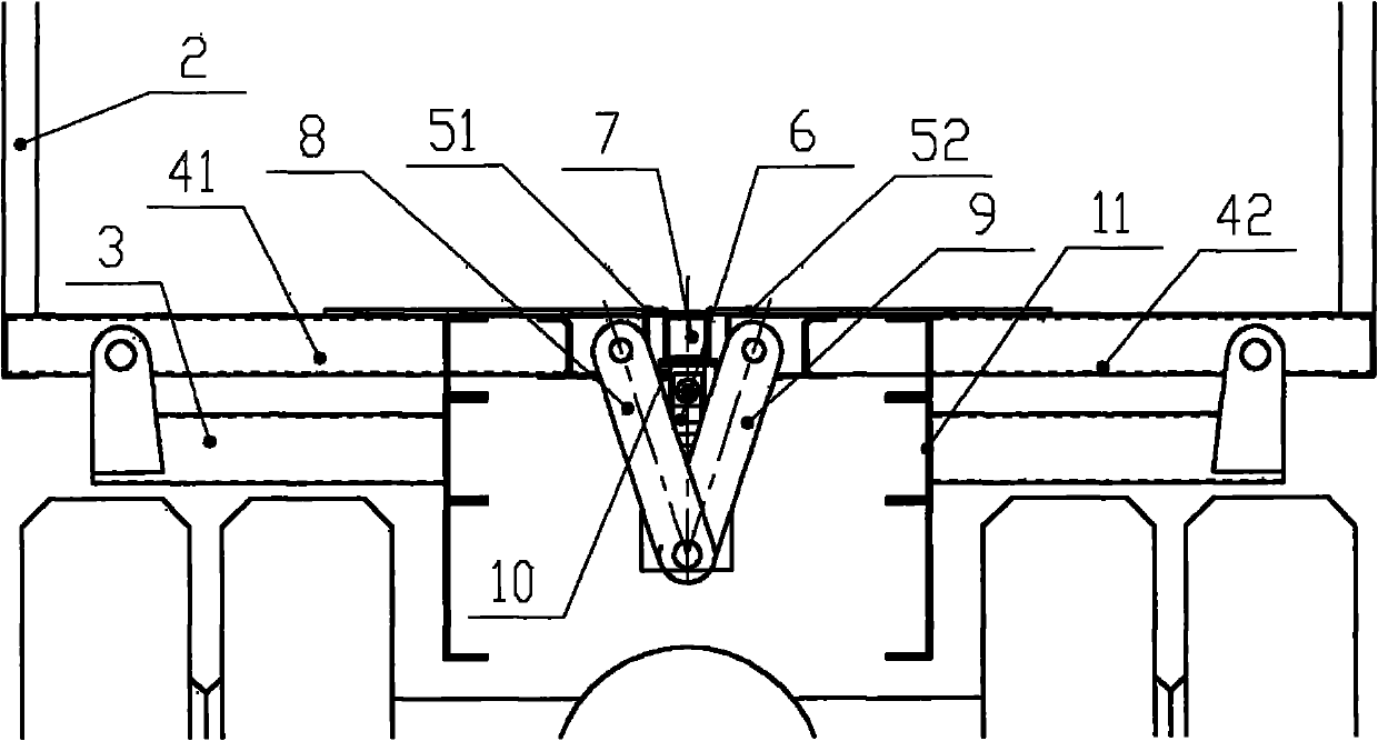
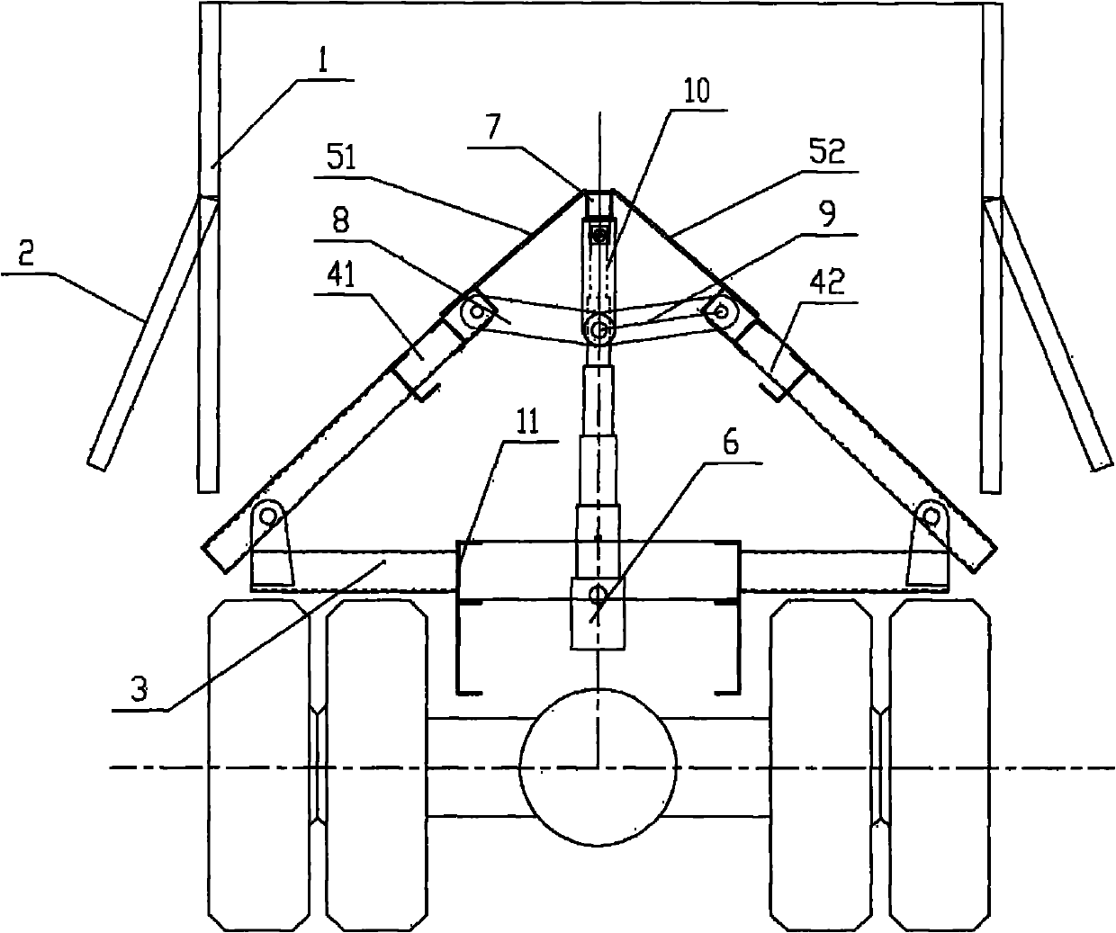
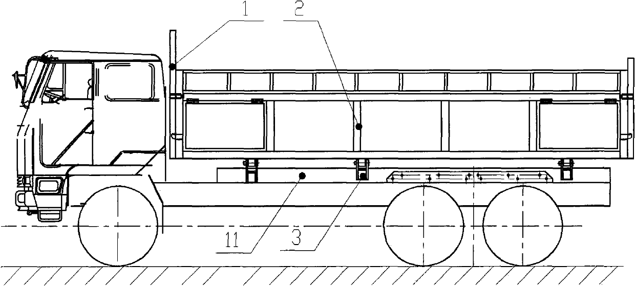
[0028] figure 1 and figure 2 It is a front view of an embodiment of the dump truck of the present invention, image 3 It is a side view, as shown in the figure, the dump truck of the present invention includes a compartment 1, the left and right sides of the compartment 1 are provided with compartment left and right panels 2, and the tops of the compartment left and right panels 2 are respectively connected to the compartment above it. The frame or the side panels are hinged so that the left and right panels 2 can be opened to the outside, and then the goods can be unloaded from the left and rig...


PUM


Abstract

The invention provides a dumper for unloading a material on two sides by lifting the middle of a bottom plate of a carriage. The dumper comprises a bottom plate longitudinal beam, a left movable bottom plate, a right movable bottom plate, a left cover plate and a right cover plate which are positioned on left and right sides of the bottom plate longitudinal beam, and a lifting mechanism, wherein the lifting mechanism comprises an ejector rod which can freely stretch to lift, and is fixed on an auxiliary frame and positioned under the bottom plate longitudinal beam; the dumper is characterizedin that: a transverse beam which is transversely arranged in the left and right direction is fixed on the auxiliary frame; the left side of the left movable bottom plate and the right side of the right movable bottom plate are hinged with left and right sides of the transverse beam respectively; the right side of the left cover plate is hinged with the bottom plate longitudinal beam; the lower surface of the left cover plate is lapped with the upper surface of the left movable bottom plate; the left side of the right cover plate is hinged with the bottom plate longitudinal beam; the lower surface of the right cover plate is lapped with the upper surface of the right movable bottom plate; the top end of the ejector rod of the lifting mechanism is fixedly connected with the lower side face of the bottom plate longitudinal beam; the dumper also comprises a loading and unloading mechanism comprising one or more groups of structures of supporting arms, left side arms and right side arms which are arranged in the longitudinal direction and are in profile distribution; the supporting arms are positioned under the bottom plate longitudinal beam and the upper ends of the supporting arms are fixed on the lower side face of the bottom plate longitudinal beam; and the left ends of the left side arms are hinged with the right side of the left movable bottom plate.

Description

technical field [0001] The invention belongs to the category of freight vehicles, and in particular relates to a dump truck in which the middle part of the bottom plate of the carriage is lifted to discharge material on both sides. Background technique [0002] As a cargo transportation job, dump trucks are widely used due to their high degree of mechanization for unloading. However, the structure of the loading and unloading mechanism of the dump truck in the prior art is complex, easy to wear, and the power required for unloading is relatively large, resulting in increased manufacturing costs, use costs and maintenance costs of the dump truck. Contents of the invention [0003] In order to overcome the above-mentioned defects in the prior art, the present invention provides a dump truck with simple structure, durability and labor saving. [0004] Technical solutions: [0005] Disclosed is a dump truck for double-side discharge by lifting the middle part of the floor of...

Claims


Application Information

Patent Timeline
IPC IPC(8): B60P1/28B60P1/16B60P1/48
Inventor 杨展路赵岩
Owner 孙景文
Learn More