
Self-propelled wheel

A self-propelled wheel and tire technology, applied in hydropower, engine components, machines/engines, etc., can solve the problems of low liquid utilization, uncompact structure, and low space utilization, so as to save resources, protect the environment, and reduce heat. pollution effect

Inactive Publication Date: 2011-07-06
李树森
View PDF0 Cites 0 Cited by
  • Summary
  • Abstract
  • Description
  • Claims
  • Application Information

AI Technical Summary

Problems solved by technology

[0003] In order to solve the problems of low utilization rate of liquid, low space utilization rate and uncompact structure of floating machines and other equipment, the invention provides a self-propelled wheel

Method used


Image

  • Self-propelled wheel
  • Self-propelled wheel
  • Self-propelled wheel

Examples


Embodiment Construction

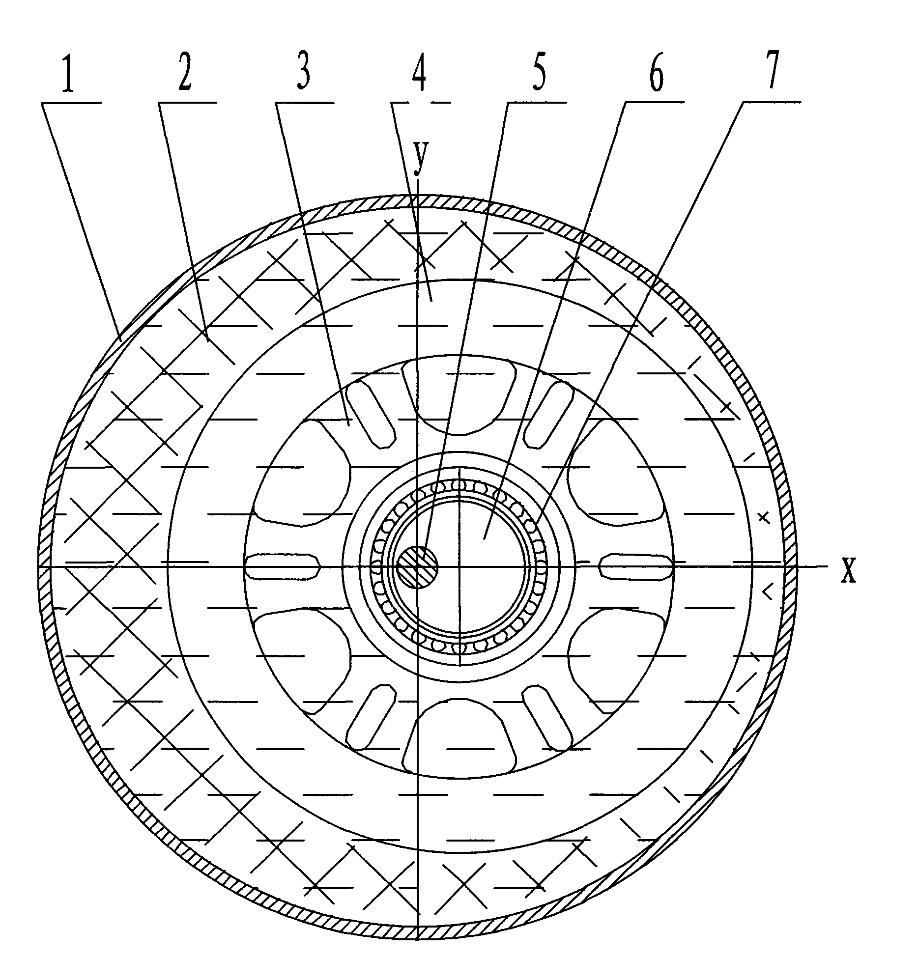
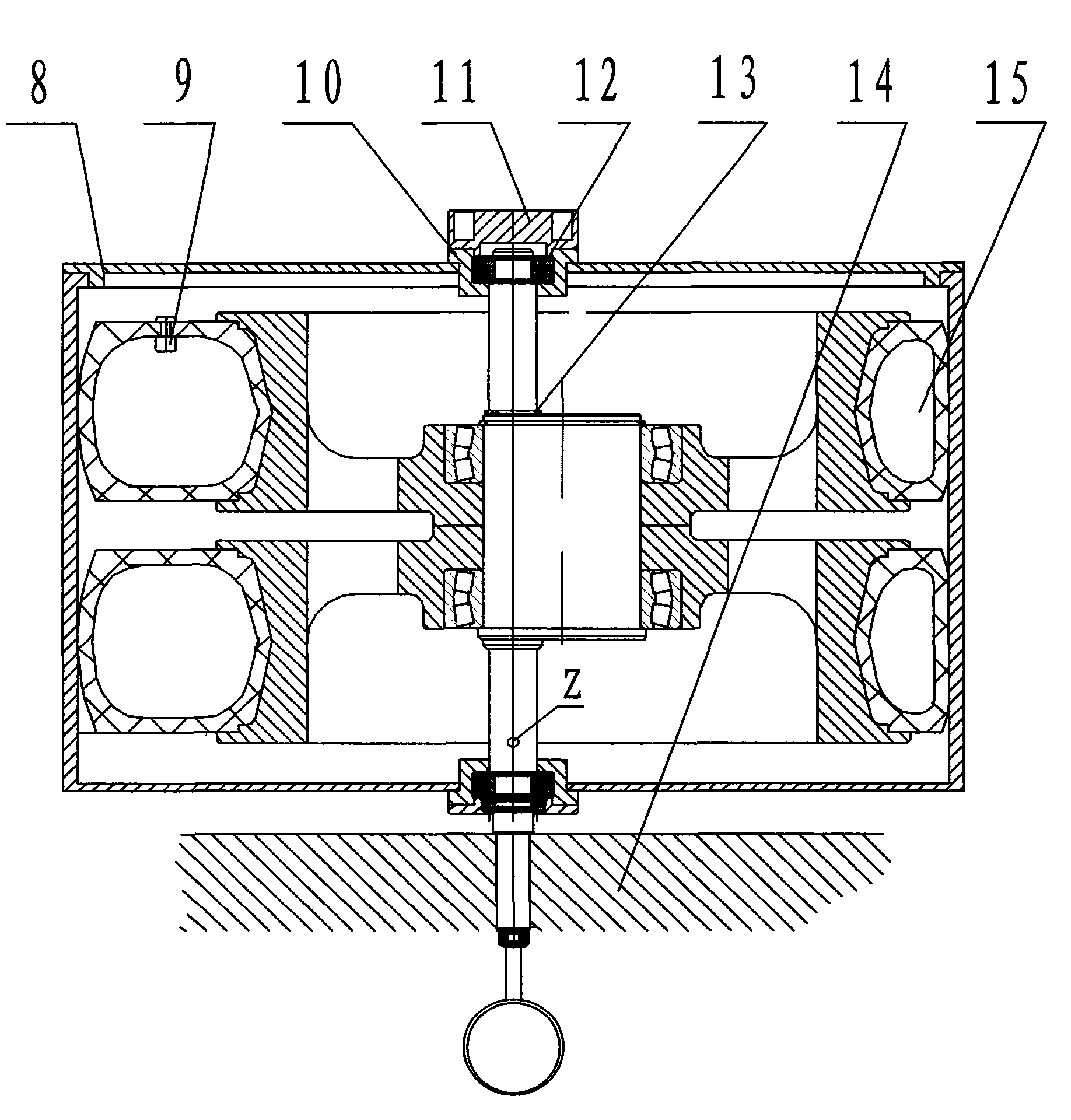
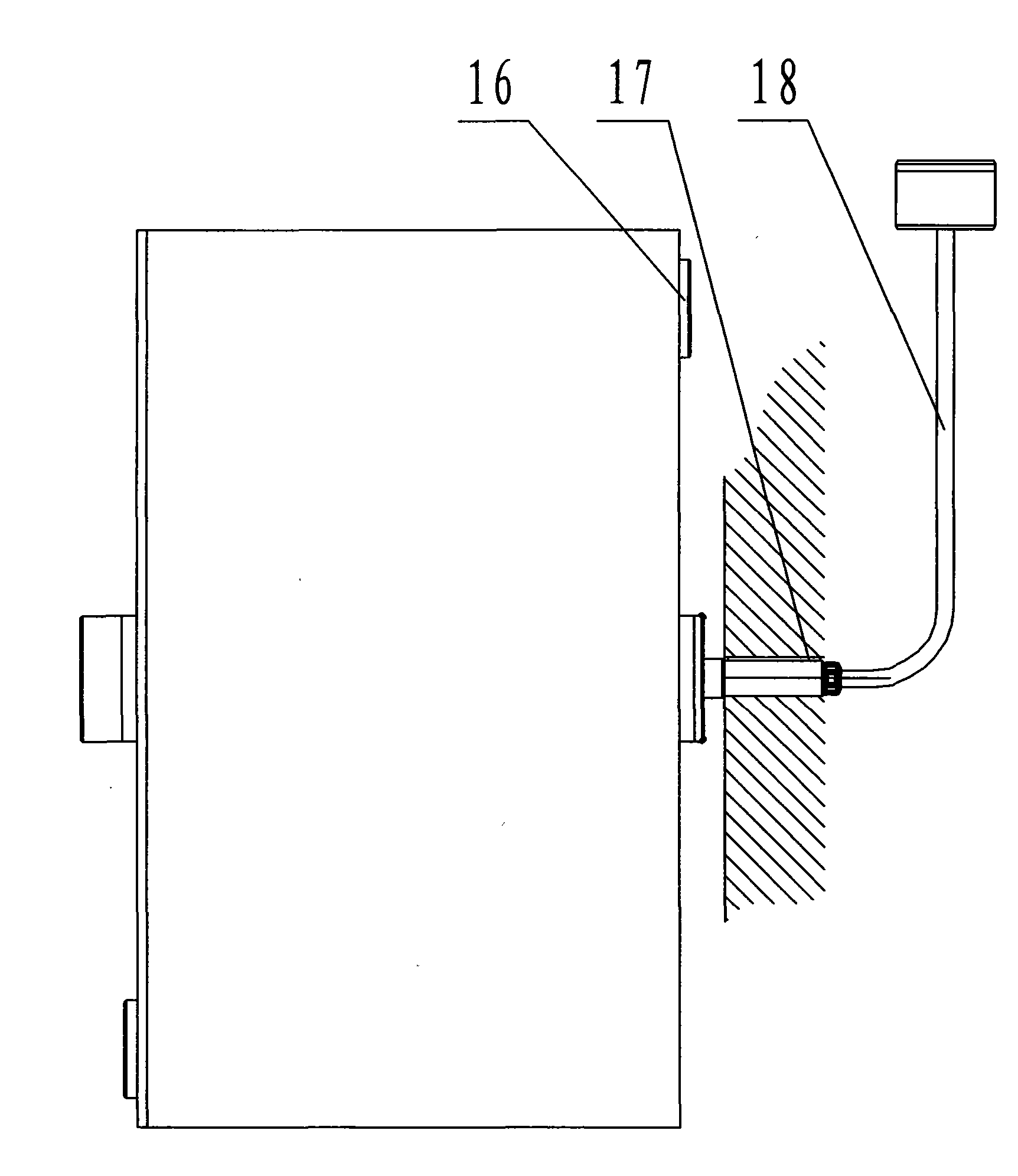
[0010] In the figure, 1. Wheel shell, 2. Tire, 3. Hub, 4. Liquid, 5. Fixed shaft, 6. Eccentric shaft, 7. Bearing, 8. Wheel shell cover, 9. Air valve, 10. Bearing seat, 11. Counter wheel, 12. Bearing, 13. Circlip, 14. Fixing frame, 15. Gas, 16. Cover, 17. Key, 18. Filling pipe.

[0011] The structure of the bicycle wheel is as attached figure 1 to attach image 3 As shown, on the fixed frame (14), a stationary fixed shaft (5) is equipped with a key (17) and a keyway. The shaft head is processed with a liquid hole communicating with the hole Z, so that the liquid (4) can be added to the wheel housing (1) through the liquid filling pipe (18), and assembled through the bearings (12) on both sides of the fixed shaft (5) In the airtight wheel housing composed of the wheel housing (1), the wheel housing cover (8) and the bearing seat (10), the eccentric shaft (6) passes through the boss of the fixed shaft (5), the key and the circlip (13 ) is positioned in the middle of the fixed ...


PUM


Abstract

The invention provides a self-propelled wheel relying on the joint action of liquid buoyancy force and liquid weight to drive a wheel tire and a wheel hull to work, which is mainly used for driving a power generator to generate power and driving other mechanical equipment to work, and belongs to the field of engines. In an airtight wheel hull body arranged on the two sides of a fixing shaft and assembled through bearings, the wheel tire and a wheel hub are assembled on an eccentric shaft through bearings, so that the right side of the wheel tire inflated with low pressure gas is pressed flat; liquid is filled in the wheel hull body; and while liquid can produce buoyancy force on the wheel tire and the buoyancy force on the left side of the wheel tire is enabled to be larger than the buoyancy force on the right side of the wheel tire, the weight of the liquid on the left side in the wheel hull body is enabled to be smaller than the weight of the liquid on the right side in the wheel hull body, so as to impel the wheel hull and the wheel tire to together rotate clockwise. The self-propelled wheel has the remarkable characteristics that with the help of the characteristic that the wheel tire is soft and can produce elastic deformation, the wheel tire and the wheel hub are driven to work by utilizing the liquid buoyancy force, and the wheel hull body is driven to work by utilizing the liquid weight, so that the self-propelled wheel can be jointly driven to rotate in a limited space by relying on the buoyancy force and the gravity which are two acting forces opposite in direction.

Description

technical field [0001] The invention relates to a self-propelled wheel which drives a tire and a wheel shell to run by the joint action of liquid buoyancy and liquid weight, belongs to the field of engines, can be used to drive a generator to generate electricity, and can also be manufactured as a wheel of a simple transport vehicle. Background technique [0002] At present, there is no engine that relies on the combined action of liquid buoyancy and liquid weight to drive machinery to rotate, thereby driving generators to generate electricity or other mechanical equipment to operate. Only floating machines and other equipment that utilize the buoyancy of liquid. The utilization rate is low, the space utilization rate is low, and the structure is not compact. Contents of the invention [0003] In order to solve the problems of low utilization rate of liquid, low space utilization rate and uncompact structure of equipment such as floating machines, the invention provides a ...

Claims


Application Information

Patent Timeline
Patent Type & Authority Applications(China)
IPC IPC(8): F03B17/02
CPCY02E10/20
Inventor 李树森
Owner 李树森
Learn More