
LED lamp

A technology for LED lamps and LED light sources, which is applied to cooling/heating devices of lighting devices, lighting and heating equipment, semiconductor devices of light-emitting elements, etc. The effect of heat conduction path, improving light utilization rate and uniform heat distribution

Inactive Publication Date: 2011-07-06
FOSHAN COSBRIGHT OPTO ELECTRONICS CO LTD
View PDF4 Cites 5 Cited by
  • Summary
  • Abstract
  • Description
  • Claims
  • Application Information

AI Technical Summary

Problems solved by technology

[0005] In order to solve the technical problems of uneven brightness and easy glare in the prior art LED downlights, the present invention proposes an LED lamp with energy saving, environmental protection, long life and simple and compact structure.

Method used


Image

  • LED lamp
  • LED lamp
  • LED lamp

Examples


Embodiment Construction

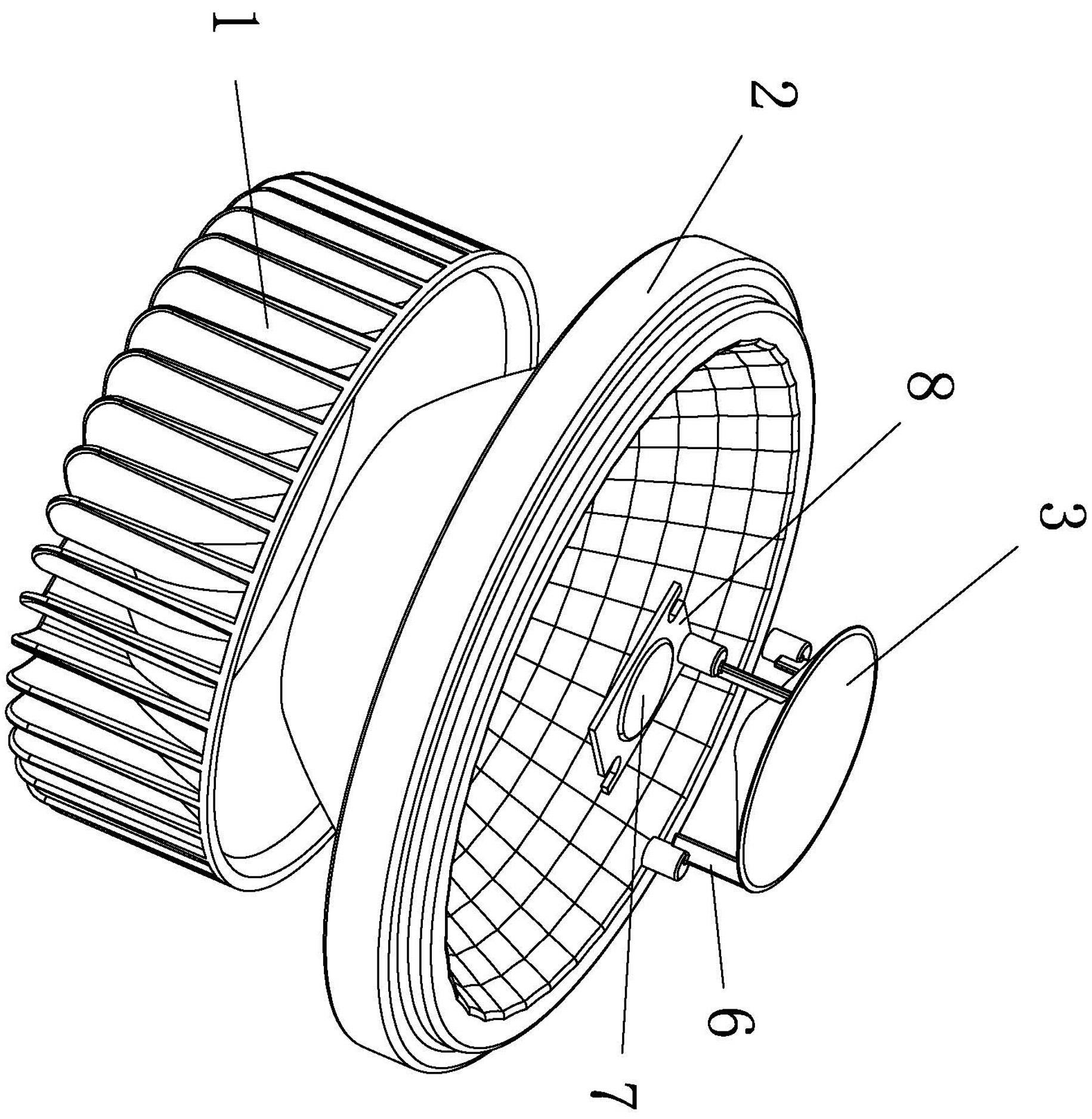
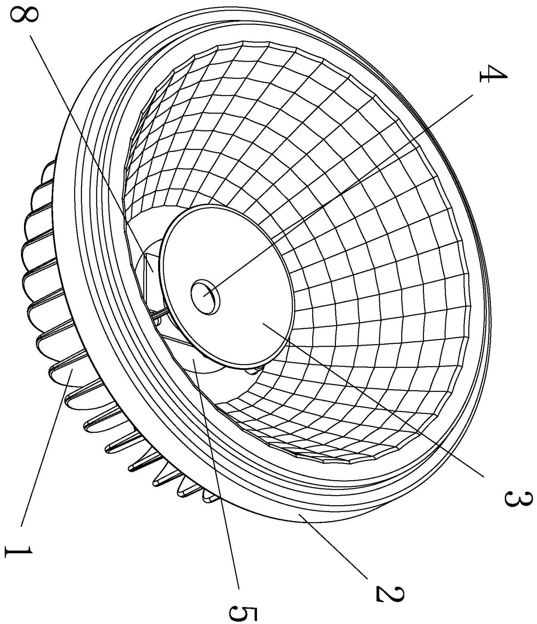
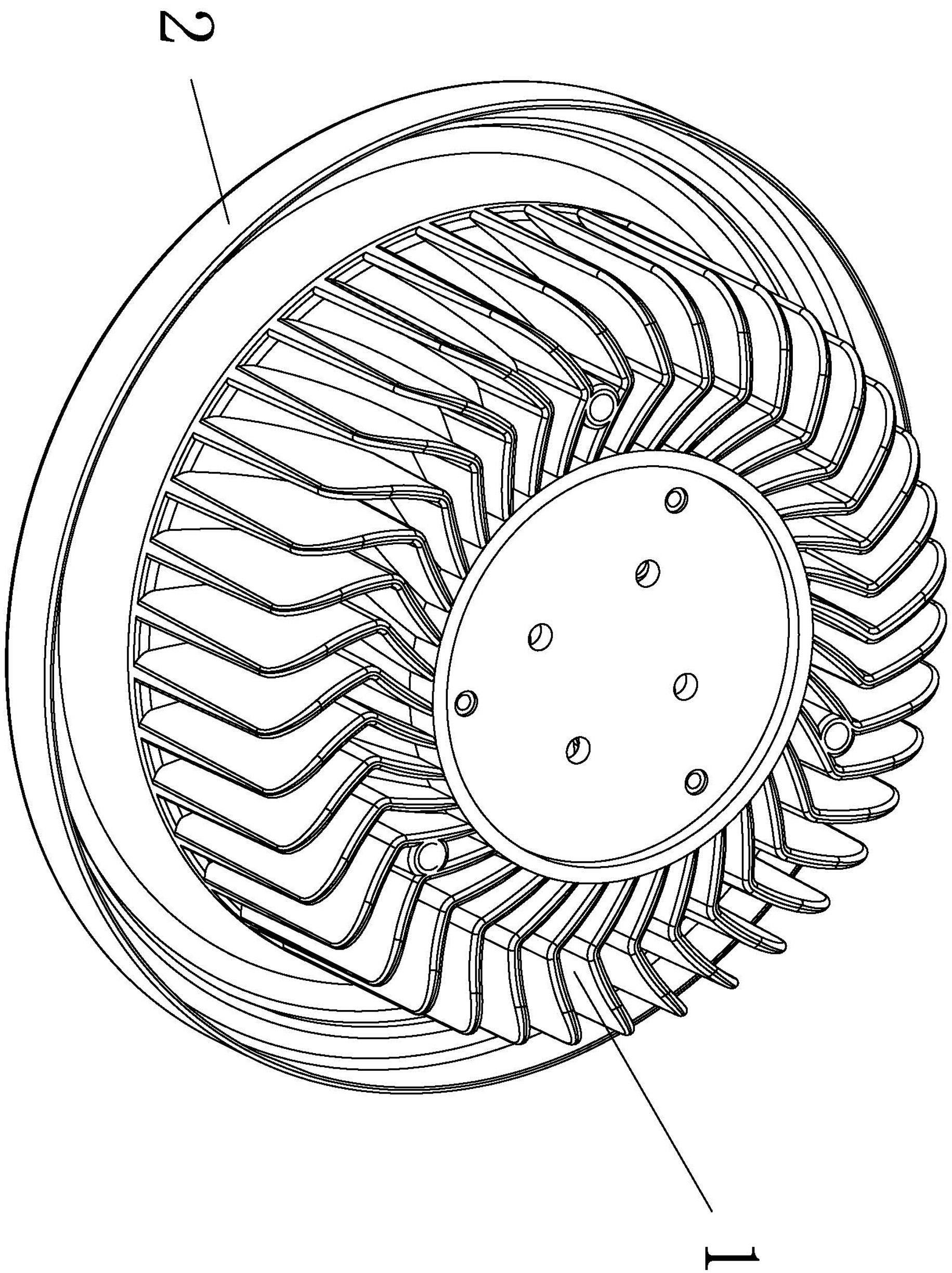
[0020] Please read figure 1 , figure 2 and image 3 , a preferred embodiment of an LED lamp proposed by the present invention, which includes a hollow radiator 1 and a reflective cup 2 adapted to the inner cavity of the radiator. The bottom of the reflector 2 is provided with a through hole 5, and the bottom of the inner cavity of the radiator 1 is closely connected with a control circuit board 8, and the control circuit board is provided with at least one LED light source 7, and the LED light source is located in the through hole of the reflector 2. 5 in. In this embodiment, above the through hole 5 in the reflective cup 2 is provided a second reflective cup 3 in the shape of a parabola, and the second reflective cup 3 is connected and fixed to the radiator 1 through three pillars 6 . The bottom of the second reflection cup 3 is provided with a small hole 4 facing the LED light source 7 . The radiator 1 is a hollow cylinder with one end closed and one end open, and its i...


PUM


Abstract

The invention discloses an LED lamp which can be used for the commercial illumination of offices, markets, subways, libraries, banks, hotels, and the like. The LED lamp comprises a hollow heat radiator (1) and a reflecting cup (2) which is adapted to an inner cavity of the heat radiator, wherein the bottom of the reflecting cup (2) is provided with a through hole (5); the bottom of the inner cavity of the heat radiator (1) is provided with a control circuit board (8); at least one LED light source (7) is arranged on the control circuit board; and the LED light source is positioned in the through hole (5) of the reflecting cup (2). According to the invention, as the LED light source for generating a heat source is directly connected with the heat radiator, the heat transfer path is shortened and the heat conduction efficiency is greatly improved, so that the temperature of the lamp is rapidly reduced to delay the light attenuation and prolong the service life.

Description

technical field [0001] The invention relates to lighting fixtures, in particular to an LED reflector lamp which can be used for commercial lighting in offices, shopping malls, subways, libraries, banks, hotels and the like. Background technique [0002] Due to the outstanding advantages of LED (Light Emitting Diode, light emitting diode), such as energy saving, environmental protection, long life, simple structure, and convenient shape, it has gradually replaced traditional high-voltage halogen lamps and is widely used in various lighting equipment. In actual production, one or several LEDs are installed on the light source panel located in the lamp housing as the light source to achieve the required brightness and power. The light emitted by the LED is refracted by the reflector set in the lamp housing and then projected out. The more LEDs you set, the brighter and more powerful your lamps will be. [0003] However, LED lamps generate a lot of heat when they work, and the ...

Claims


Application Information

Patent Timeline
Patent Type & Authority Applications(China)
IPC IPC(8): F21S2/00F21V7/06F21V17/00F21V19/00F21V29/00F21Y101/02
CPCF21S2/00F21V17/00F21V29/00F21V7/06F21V7/0041F21K9/00F21V19/00F21V7/20F21V29/505
Inventor 郭平龙海奔
Owner FOSHAN COSBRIGHT OPTO ELECTRONICS CO LTD
Learn More