Eureka AIR delivers breakthrough ideas for toughest innovation challenges, trusted by R&D personnel around the world.

Quantum dot-based color-converted light-emitting device and method for manufacturing the same

Active Publication Date: 2019-03-14
MAVEN OPTRONICS CO LTD
View PDF0 Cites 7 Cited by
  • Summary
  • Abstract
  • Description
  • Claims
  • Application Information

AI Technical Summary

Benefits of technology

This patent is about a new quantum dot-based color-converted light-emitting device and method of manufacturing it. The device has low thermal resistance and good heat dissipation, which reduces the operating temperature of the quantum dot material and improves its stability. The device also has a good moisture barrier to prevent water vapor and oxygen from reaching the quantum dot material and an improved photo-oxidation reaction process. Additionally, the device has a polymer matrix material that is specifically chosen for binding the quantum dot material, which helps to isolate it from the polymer matrix material used for binding the phosphor material, thereby avoiding curing process incompatibility or material incompatibility.

Problems solved by technology

Although a light-emitting device using a quantum dot material has many advantages, there are still some problems to be improved or overcome in practice.
For example, the thermal stability of quantum dot materials is poor, and their performance is significantly degraded when operated in high-temperature environments (e.g., environments greater than 70° C.).
Therefore, the heat generated during the operation of the LED semiconductor chip may greatly attenuate the performance of the quantum dot material.
Moreover, generation of oxides will create more structural defects on the quantum dots, and the structural defects will cause the electrons and holes to undergo a non-radiative electron-hole recombination during the photoluminescent process.
Therefore, the photo-oxidation phenomenon of the quantum dot material will also cause the luminous intensity to decrease, and eventually the quantum dots will not be effective.
However, not all quantum dot materials can be uniformly dispersed inside and compatible with the commonly used polymer matrix materials.
Therefore, surface modification, selection of proper polymer matrix materials, and manufacturing process compatibility between different polymer matrix materials in fabricating a quantum dot-based color-converted light emitting device have also become important technical challenges.
Therefore, improving or overcoming the above technical issues in order to use quantum dot materials in a color-converted light-emitting device is an imminent technical challenge in the LED industry.
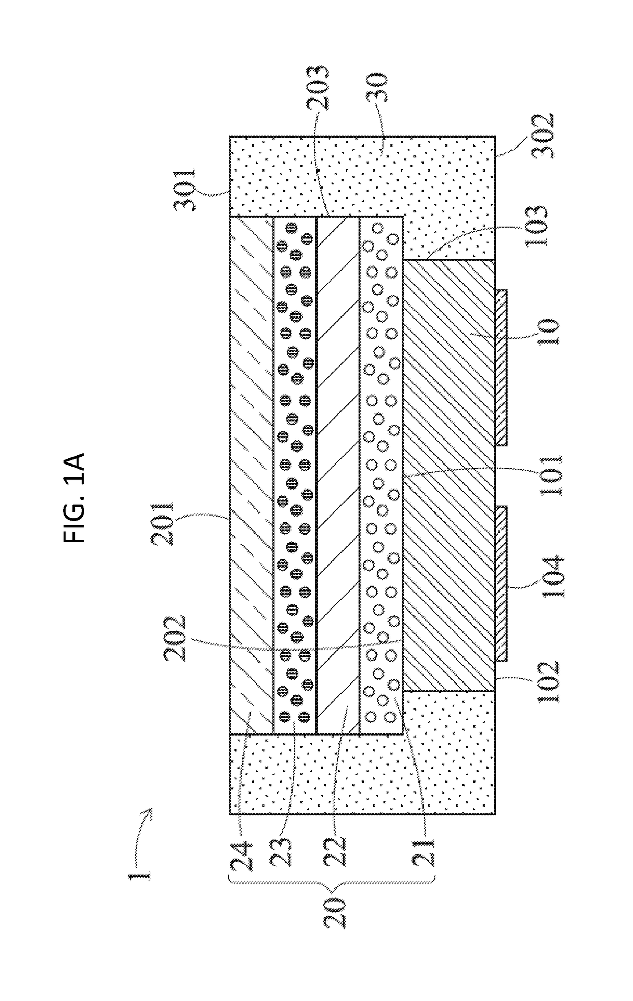
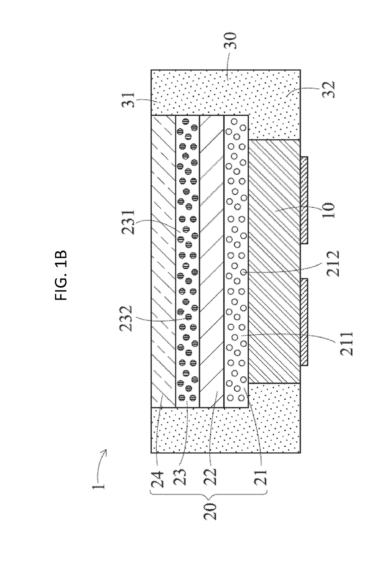
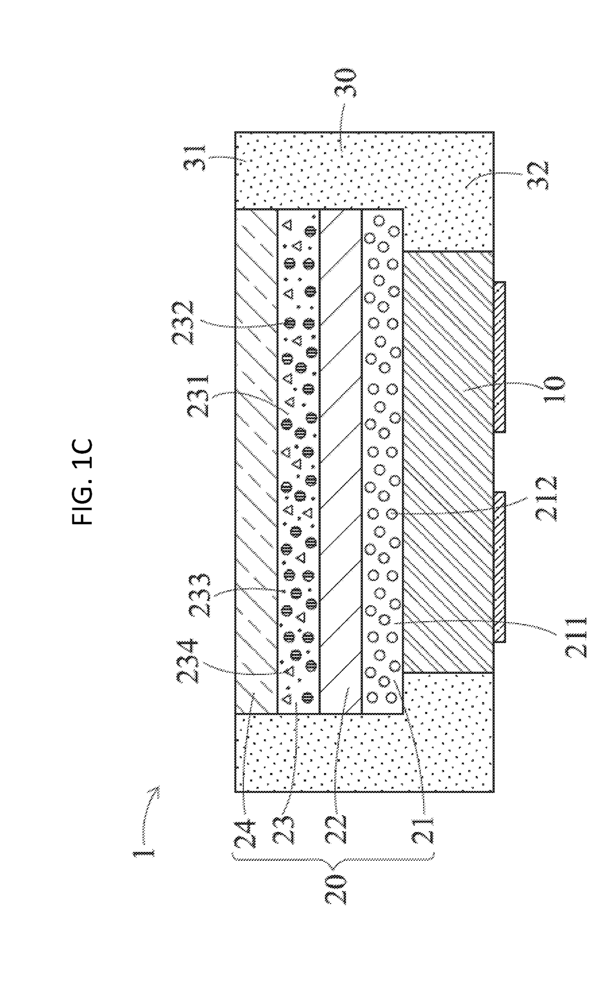
(3) Both of the optically transparent moisture barrier layer and the moisture-barrier reflective structure have low water vapor transmission rate (WVTR), so that the external water vapor and oxygen will not readily penetrate into the light-emitting device to be in contact with the quantum dot material within the second photoluminescent layer.

Method used


Image

  • Quantum dot-based color-converted light-emitting device and method for manufacturing the same
  • Quantum dot-based color-converted light-emitting device and method for manufacturing the same
  • Quantum dot-based color-converted light-emitting device and method for manufacturing the same

Examples


Embodiment Construction

Definitions

[0027]The following definitions apply to some of the technical aspects described with respect to some embodiments of the disclosure. These definitions may likewise be expanded upon herein.

[0028]As used herein, the singular terms “a,”“an,” and “the” may include plural referents unless the context clearly dictates otherwise. Thus, for example, reference to a layer can include multiple layers unless the context clearly dictates otherwise.

[0029]As used herein, the term “set” refers to a collection of one or more components. Thus, for example, a set of layers can include a single layer or multiple layers. Components of a set also can be referred to as members of the set. Components of a set can be the same or different. In some instances, components of a set can share one or more common characteristics.

[0030]As used herein, the term “adjacent” refers to being near or adjoining. Adjacent components can be spaced apart from one another or can be in actual or direct contact with ...


PUM


Abstract

A light-emitting device includes a flip-chip LED semiconductor chip to provide a primary light, a photoluminescent (PL) structure disposed on the LED semiconductor chip and a moisture-barrier reflective structure covering a chip-edge surface of the LED semiconductor chip and a photoluminescent-side surface of the PL structure. The sequentially stacked PL structure includes a first PL layer, a transparent isolation layer, a second PL layer and a transparent moisture barrier layer. For example, the LED semiconductor chip emits a blue light, the first PL layer includes a red phosphor material, and the second PL layer includes a green quantum dot (QD) material. Therefore, the red phosphor material of the first PL layer can convert a portion of the higher-energy-level blue light into a lower-energy-level converted red light, so as to reduce an intensity of an unconverted portion of the blue light reaching the green QD material within the second PL layer.

Description

CROSS-REFERENCES TO RELATED APPLICATIONS[0001]This application claims the benefit of and priority to Taiwan Patent Application No. 106130827 filed on Sep. 8, 2017, and Chinese Patent Application No. 201710812987.0 filed on Sep. 11, 2017, the disclosures of which are incorporated herein by reference in their entirety.BACKGROUNDTechnical Field[0002]The present disclosure relates to a chip-scale packaging light-emitting device and a method of manufacturing the same, and more particularly to a chip-scale packaging light-emitting device using a green quantum dot material and a red phosphor material, and a method of manufacturing the same thereof.Description of the Related Art[0003]A quantum dot (QD) material encompasses a semiconductor nano-crystal material with its particle size usually between about 1 nm and about 50 nm. While being irradiated by a high-energy-level light, due to Quantum confinement effect, a quantum dot material can convert a portion of incident light into another low...

Claims


Application Information

Patent Timeline
IPC IPC(8): H01L33/50H01L33/60H01L33/64
CPCH01L2933/0058H01L33/641H01L33/504H01L33/505H01L2933/005H01L33/644H01L2933/0075H01L2933/0091H01L2933/0041H01L33/60H01L33/48H01L33/502H01L33/52
Inventor CHEN, CHIEH
Owner MAVEN OPTRONICS CO LTD
Why Eureka
Eureka Blog
Learn More