LED light structure

Inactive Publication Date: 2015-02-05
KONINKLIJKE PHILIPS ELECTRONICS NV +1
View PDF3 Cites 1 Cited by
  • Summary
  • Abstract
  • Description
  • Claims
  • Application Information

AI Technical Summary

Benefits of technology

This patent text describes a light structure that uses different types of LEDs to emit light in different colors. The LEDs are mounted on a heat sink using a PCB, and they are arranged in rows with alternating rows of different types of LEDs. This arrangement allows for the mixing of colors in the optics. The thickness of the soldering material used in the process is controlled to accommodate any thermal expansion mismatch and has a low thermal resistance. The technical effect of this invention is to provide a light structure that can produce high-quality light with precise color control.

Problems solved by technology

The heat resistance from the LEDs to the heat sink (or more precisely from the LEDs to the ambient air) is thereby extremely low.
In case a LED or bond wire is damaged, only that tile is wasted.

Method used


Image

  • LED light structure
  • LED light structure
  • LED light structure

Examples


Embodiment Construction

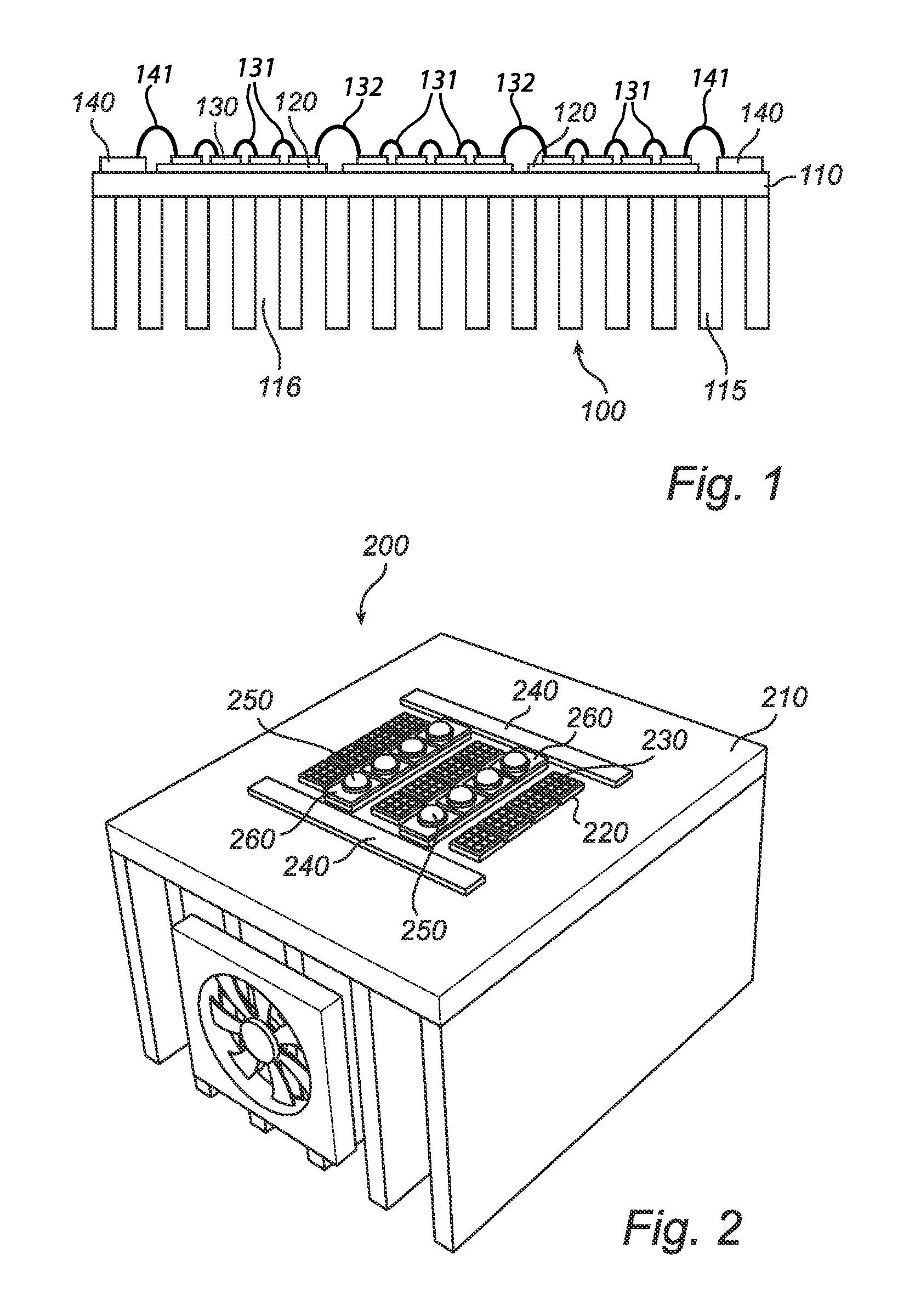
[0031]FIG. 1 is a schematic side view of an embodiment of the inventive light structure. The light structure 100 comprises a heat sink 110. The heat sink 110 is arranged to cool the light structure 100 by dissipating heat into the surrounding air. This is accomplished through increasing the surface area in contact with the cooling fluid surrounding it, such as the air. The heat sink 110 can, e.g., be a heat exchanger such as those used in refrigeration and air conditioning systems or a radiator such as those used in cars. In one embodiment, the heat sink has cooling fins 115, as is disclosed in FIG. 1. The cooling fins 115 comprise cooling air 116. The heat sink 110 can, e.g., be made of copper.

[0032]The light structure 100 further comprises a plurality of ceramic tiles 120. The ceramic tiles 120 can, e.g., be made of AlN (aluminum nitride). AlN has about the same thermal expansion coefficient as the LEDs. The inventors have found through testing that the thermal expansion mismatch ...


PUM


Abstract

The disclosed embodiments relate to a light structure (100, 200, 300, 400) comprising a heat sink (110, 210, 310, 410), a plurality of ceramic tiles (120, 220, 320, 420), at least one LED (130, 230, 330, 430) arranged on each ceramic tile (120, 220, 320, 420), a plurality of wires connecting the LEDs (130, 230, 330, 430), the plurality of ceramic tiles (120, 220, 320, 420) being in direct contact with the heat sink (110, 210, 310, 410).

Description

FIELD OF THE INVENTION[0001]The present invention relates to an LED light structure.BACKGROUND OF THE INVENTION[0002]The most important value driver for multicolor LED spot modules is the output per mm2 which is very much determined by heat management. In order to achieve a high light output per mm2, the heat transfer from the LEDs to the environment must be excellent. In addition, the fraction of active LED area must be as large as possible (LEDs closely packaged). Good heat transfer and high LED density are thus important value drivers for LED spots.[0003]Systems exist in which LED chips are mounted on a substrate (in general a ceramic substrate) and this substrate is mounted on a PCB (in most cases a Metal Core PCB) and this PCB is mounted on a heat sink Mounting LED chips directly on a PCB is not preferred because of the high mismatch of the thermal expansion coefficients of Copper and the LED chip.[0004]A disadvantage with mounting one or more PCBs on a heat sink is that the in...

Claims


Application Information

Patent Timeline
IPC IPC(8): F21V19/00F21V29/00
CPCF21V19/005F21V29/2206F21V29/30F21V19/0025F21V29/2293F21V29/763F21V29/83F21V29/86F21V29/89H01L2224/48091H01L2224/48137F21V23/006F21Y2113/00F21V29/67F21Y2105/10F21Y2115/10H01L2924/00014
Inventor VERBRUGH, STEFAN MARCUSKURT, RALPHDUMOULIN, RAIMOND LOUIS
Owner KONINKLIJKE PHILIPS ELECTRONICS NV
Why Eureka
Try Eureka