

Thermal conductive silicone composition, semiconductor device, and method for manufacturing the same
- Summary
- Abstract
- Description
- Claims
- Application Information
AI Technical Summary
Benefits of technology
Problems solved by technology
Method used
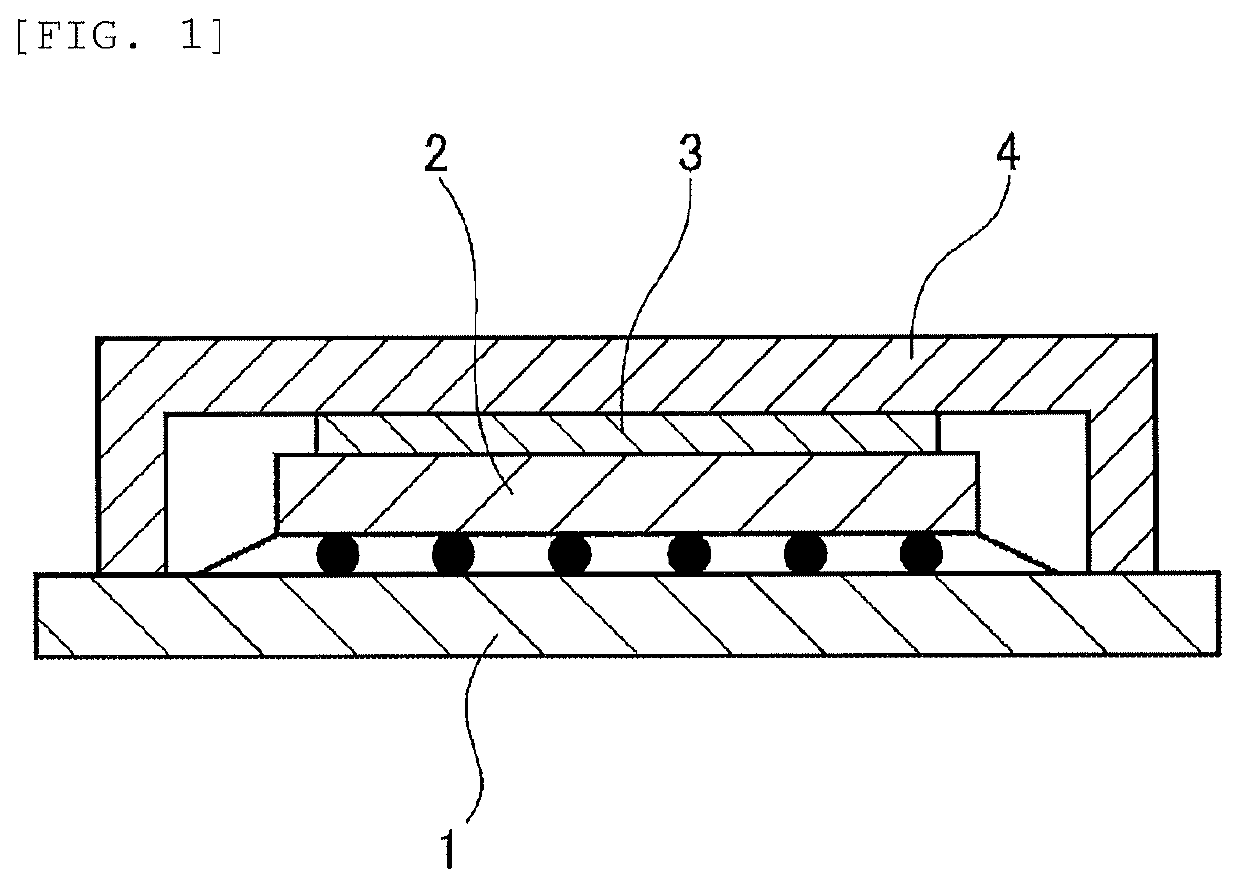
Image

Examples
example
[0093]Hereinafter, the present invention will be described further specifically by using Examples and Comparative Examples for the purpose of clarifying the advantageous effects of the present invention further. However, the present invention is not limited thereto.
[0094]Viscosity, thermal resistance, and Asker C hardness were measured as follows.
[0095]The absolute viscosity of the composition was measured by using a Malcolm viscometer (type PC-1TL) at 25° C.
[0096]Each composition was sandwiched between two aluminum plates of #12.7 mm, and then left in an oven of 150° C. for 90 minutes in a state of having a pressure of 0.35 Mpa applied to heat and cure each composition. Thus, test specimens for thermal resistance measurement were made, and the thermal resistance was measured. Note that this thermal resistance measurement was carried out using NanoFlash (LFA447 manufactured by NETZSCH).
(Asker C Hardness)
[0097]Each composition of the Examples 1 to 14 an...
examples 1 to 14
[Examples 1 to 14] and [Comparative Examples 1 to 6]
[0101]The components were mixed according to the compositions shown in the following Tables 1 to 3 in the following manner to obtain the compositions of Examples 1 to 14 and Comparative Examples 1 to 6.
[0102]That is, the components (A) and (D) were placed in a 5-liter planetary mixer (manufactured by INOUE MFG., INC.), the components (C), (E), and (F) were added, and were mixed at 25° C. for 1.5 hours. Next, the component (B) was added and mixed so as to homogenize the mixture. The above-described tests were performed on the obtained compositions. Tables 1 to 3 show the results.
TABLE 1Example 1Example 2Example 3Example 4Example 5Example 6Example 7(A)100100100100100100100(B)5555555(C)6.76.76.76.76.76.76.7(D-1)900——————(D-2)—1200600900—1900350(D-3)————900——(E-1)4.54.54.54.54.54.54.5(E-2)———————(E-3)———————(E-4)———————(E-5)———————(E-6)———————(E-7)———————(F)0.170.170.170.170.170.170.17Viscosity100150507015040012(Pa · s)Thermal0.70.82.0...
PUM
| Property | Measurement | Unit |
|---|---|---|
| Temperature | aaaaa | aaaaa |
| Length | aaaaa | aaaaa |
| Length | aaaaa | aaaaa |
Abstract
Description
Claims
Application Information