
Thermally conductive silicone composition and semiconductor device

Inactive Publication Date: 2019-01-03
SHIN ETSU CHEM IND CO LTD
View PDF5 Cites 1 Cited by
  • Summary
  • Abstract
  • Description
  • Claims
  • Application Information

AI Technical Summary

Benefits of technology

The present invention relates to a thermally conductive silicone composition with good thermal conductivity. This makes it suitable for use in semiconductor devices.

Problems solved by technology

Especially, in the case of an integrated circuit element such as a CPU used in a personal computer, the amount of heat generation has increased due to a higher frequency of operation, which makes a countermeasure(s) against heat a critical issue.
Meanwhile, those exhibiting a low thermal resistance have a thin BLT, and may exhibit an impaired thermal resistance after a heat cycle test, which lacks reliability.
That is, none of the above thermally conducive materials and thermally conducive greases is satisfactory in terms of dealing with heat release from an integrated circuit element such as a CPU generating heat by a larger amount in recent days.

Method used


Image

  • Thermally conductive silicone composition and semiconductor device
  • Thermally conductive silicone composition and semiconductor device
  • Thermally conductive silicone composition and semiconductor device

Examples


working example

[0089]The present invention is described in greater detail hereunder with reference to working and comparative examples for the purpose of further clarifying the effects of the invention. However, the present invention is not limited to these examples.

[0090]Tests for confirming the effects of the present invention were performed as follows.

Viscosity

[0091]The absolute viscosity of the composition was measured by a Malcolm viscometer (type: PC-1TL) at 25° C.

Thermal Conductivity

[0092]In working examples 1 to 14; and comparative examples 1 to 8, each composition was poured into a mold having a thickness of 6 mm, followed by heating the composition to 150° C. with a pressure of 0.35 MPa being applied thereto, and then using TPS-2500S manufactured by Kyoto Electronics Manufacturing Co., Ltd. to measure the thermal conductivity thereof at 25° C. In working example 15, the composition was poured into a mold having a thickness of 6 mm, and then left for seven days under a condition of 23±2° ...

working examples 1 to 15

; and Comparative Examples 1 to 8

[0119]The above components were mixed at the compounding ratios shown in the following Tables 1 to 3, and each composition in working examples 1 to 15 and comparative examples 1 to 8 was thus obtained.

[0120]Specifically, the component (A) was put into a planetary mixer (by INOUE MFG., INC.) having a volume of 5 L, followed by adding thereto the component (G) in the case of working example 4 or the component (H) in the case of working example 5. The components (B) and (C) were further added thereto, followed by performing mixing at 25° C. for 1.5 hours. Next, the component (D) was added; and the component (I) in the cases of working examples 1 to 8 and comparative examples 1 to 8 or the component (J) in the case of working example 15 was further added, followed by performing mixing so as to homogenize the components added.

TABLE 1Unit: part by massWorking example12345678A-19595959595959595A-255555555A-3B-16004800480048004800950950950B-2B-3B-4B-5B-6B-7C...


PUM

PropertyMeasurementUnit
Temperatureaaaaaaaaaa
Lengthaaaaaaaaaa
Percent by massaaaaaaaaaa

Abstract

The composition is a thermally conductive silicone composition containing the following components (A) to (C) and (D). The component (A) is an organopolysiloxane that exhibits a kinetic viscosity of 10 to 100,000 mm2 / s at 25° C., and is represented by an average composition formula (1)R1aSiO(4-a) / 2  (1)wherein R1 represents a hydrogen atom, a hydroxy group or a monovalent hydrocarbon group, and a satisfies 1.8≤a≤2.2. The component (B) is a silver powder having a tap density of not lower than 3.0 g / cm3, a specific surface area of not larger than 2.0 m2 / g, and an aspect ratio of 2.0 to 150.0. The component (C) is a thermally conductive filler other than the component (B), having an average particle size of 5 to 100 μm and a thermal conductivity of not lower than 10 W / m° C. The component (D) is a platinum-based catalyst, an organic peroxide and / or a catalyst for condensation reaction.

Description

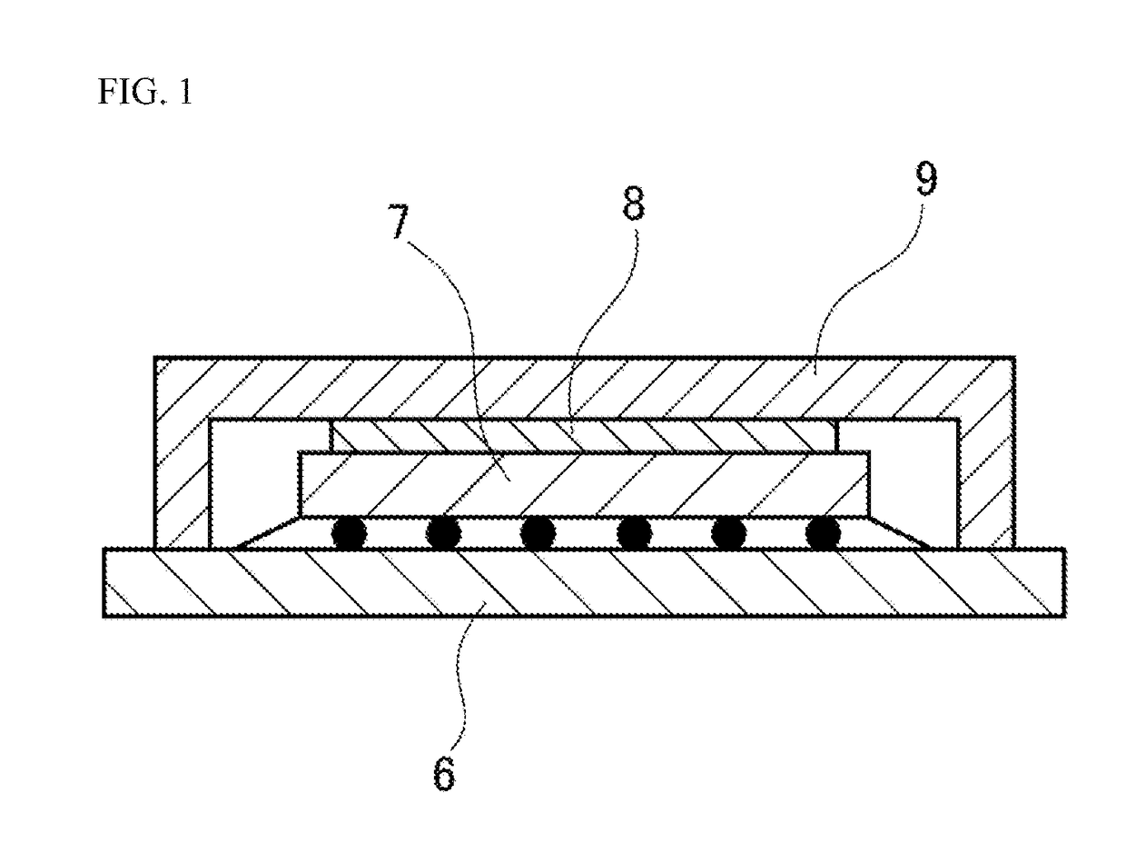
TECHNICAL FIELD[0001]The present invention relates to a silicone composition superior in thermal conductivity; and a semiconductor device.BACKGROUND ART[0002]Since most electronic parts generate heat while in use, it is required that such heat be eliminated from an electronic part to allow this electronic part to function properly. Especially, in the case of an integrated circuit element such as a CPU used in a personal computer, the amount of heat generation has increased due to a higher frequency of operation, which makes a countermeasure(s) against heat a critical issue.[0003]For these reasons, there have been proposed may methods for releasing such heat. Particularly, as for electronic parts generating large amounts of heat, there has been known a method for releasing heat by interposing a thermally conductive material such a thermally conductive grease and a thermally conductive sheet between, for example, an electronic part and a heat sink.[0004]JP-A-Hei-2-153995 (Patent docum...

Claims


Application Information

Patent Timeline
IPC IPC(8): C08L83/04C08K3/08C08K5/14H01L23/373
CPCC08L83/04C08K3/08C08K5/14H01L23/3737H01L23/3738C08K2003/0806C08K2201/006C08K2201/016C08K2201/001C08K2201/005C08K2003/0812C08L2203/20H01L23/373H01L2224/73204H01L2224/73253H01L23/3731C08L83/00C08K5/56C08K5/5425C08G77/08C08G77/12C08G77/20
Inventor AKIBA, SHOTATSUJI, KENICHI
Owner SHIN ETSU CHEM IND CO LTD
Learn More