Double-frequency antenna

A dual-frequency antenna and antenna technology, applied in antennas, resonant antennas, antenna coupling, etc., can solve the problems of low elevation gain and other issues, and achieve the effects of good grounding, cost reduction, good axial ratio bandwidth and low elevation gain

Inactive Publication Date: 2012-08-29
HARXON CORP
View PDF1 Cites 1 Cited by
  • Summary
  • Abstract
  • Description
  • Claims
  • Application Information

AI Technical Summary

Problems solved by technology

[0009] 4. Low elevation gain

Method used


Image

  • Double-frequency antenna
  • Double-frequency antenna
  • Double-frequency antenna

Examples


Embodiment Construction

[0028] The technical solutions of the present invention are further described below with reference to the accompanying drawings and specific embodiments of the description.

[0029] It should be understood that the specific embodiments described herein are only used to explain the present invention, but not to limit the present invention.

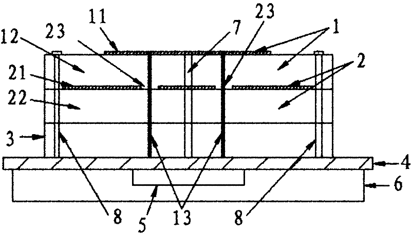
[0030] like figure 1 shown is a schematic cross-sectional view of a preferred embodiment of the dual-frequency antenna of the present invention; this embodiment includes an upper-layer microstrip antenna 1, a lower-layer microstrip antenna 2, a dielectric layer 3, a reflector 4, and a phase-shift feeder located on the back of the reflector 4. The electrical network 5 and the shielding box 6 located just below the back of the reflector 4; in the figure, 11 is the radiation patch of the upper-layer microstrip antenna 1, 12 is the dielectric substrate of the upper-layer microstrip antenna 1, and 13 is the upper-layer microstrip antenna 1 21 i...


PUM


Abstract

The invention relates to a double-frequency antenna comprising an upper-layer microstrip antenna, a lower-layer microstrip antenna, a baffle board and a phase shift feeding network, wherein the upper-layer microstrip antenna and the lower-layer microstrip antenna are fixed on the front of the baffle board through screws after being overlapped; the phase shift feeding network is positioned at the back of the baffle board; the upper-layer microstrip antenna carries out feeding through a double-feeding needle; the lower-layer microstrip antenna carries out coupled feeding through a via hole corresponding to the feeding needle of the upper-layer microstrip antenna on a radiating patch of the lower-layer microstrip antenna; and the feeding needle of the upper-layer microstrip antenna passes through the via hole to reach to the phase shift feeding network. The double-frequency antenna has a small size, a firm structure and a simple process and also has favorable axis ratio bandwidth and lowelevation gain.

Description

technical field [0001] The present invention relates to the field of antennas, in particular to a dual-frequency antenna. Background technique [0002] With the rapid development of satellite navigation technology and its wide application in various fields, higher and higher requirements have also been placed on the antenna performance of handheld receiving devices in high-precision satellite navigation and positioning systems, mainly in: [0003] 1. Good circular polarization performance [0004] In satellite communication, circularly polarized waves generally use circularly polarized signals because the attenuation of circularly polarized rain and snow is small, and the ability to penetrate the ionosphere is strong. Therefore, the antenna should also work in a good circular polarization state to better match the system. [0005] 2. Can accept multi-frequency signals [0006] The ionospheric delay is the most important factor affecting the absolute positioning of the Glo...

Claims


Application Information

Patent Timeline
Patent Type & Authority Patents(China)
IPC IPC(8): H01Q5/00H01Q23/00H01Q9/04H01Q1/52H01Q1/48H03H7/18H01Q21/30
Inventor 黄毅王春华
Owner HARXON CORP
Why Eureka
Try Eureka