Dual-polarized indoor distributed antenna

An indoor distribution, dual-polarization technology, applied in the field of mobile communications, can solve problems such as inconsistent maximum pointing, different coverage areas, serious mutual coupling of radiators, etc., to ensure consistency, meet non-correlation requirements, and high isolation Effect

Inactive Publication Date: 2011-07-06
MOBILE ANTENNA TECH SHENZHEN
View PDF4 Cites 28 Cited by
  • Summary
  • Abstract
  • Description
  • Claims
  • Application Information

AI Technical Summary

Problems solved by technology

[0004] Traditional indoor coverage antennas cannot support polarization diversity technology and MIMO (Multiple Input Multiple Output) technology. Realizing the dual polarization technology of indoor distributed antennas is a key technology to solve the capacity of the indoor distributed network coverage system of TD-SCDMA system, especially the dual Polarized omnidirectional indoor antenna technology is a key technology that restricts the capacity of indoor distributed network coverage systems. With the development of LTE (Long Term Evolution) technology, the frequency range of dual-polarized omnidirectional indoor antennas is required to be expanded. How to realize broadband dual Polarized omnidirectional indoor antenna has become the main research direction of dual polarized omnidirectional indoor antenna
[0005] The current implementation of the horizontally polarized radiator of the horizontally and vertically polarized omnidirectional indoor antenna is mainly based on the combination of symmetrical oscillators and slots. Inconsistency, resulting in different coverage of the two different polarizations of the system, and on the other hand, the mutual coupling of the radiators of the two polarizations is serious

Method used


Image

  • Dual-polarized indoor distributed antenna
  • Dual-polarized indoor distributed antenna
  • Dual-polarized indoor distributed antenna

Examples


Embodiment 2

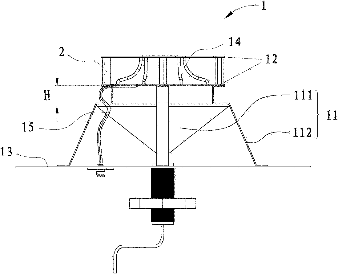
[0042] See attached Figure 3-Figure 4 As shown, the difference between embodiment two and embodiment one is:

[0043] The horizontal radiator 12 is composed of two circuit substrates, wherein the two circuit substrates are supported by a plurality of guide posts 2 to separate the two circuit substrates.

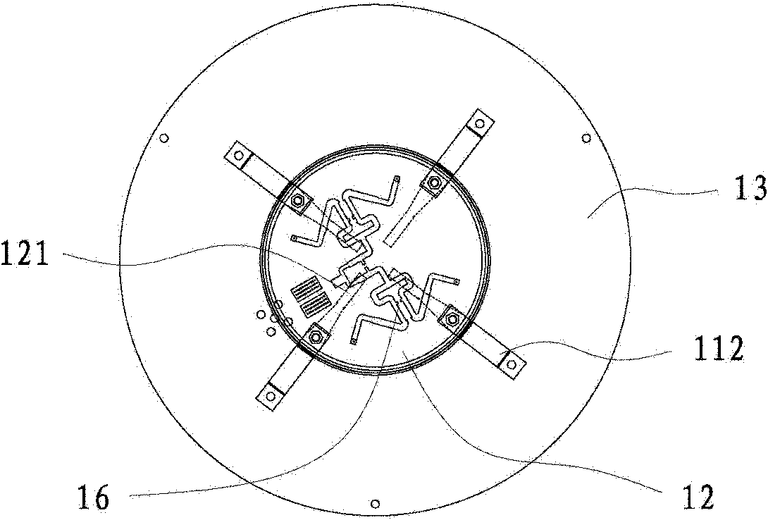
[0044] One of the circuit substrates is a double-sided circuit substrate, a plurality of ridged horn vibrators 121 are printed on one side, and a plurality of coupled microstrip lines 15 are printed on the other side; a power distribution network 16 is printed on the other circuit substrate, and the power distribution network 16 and Each coupled microstrip line 15 cooperates with the ridge horn oscillator 121 to couple and excite signals of equal amplitude and same phase, and the corresponding ports between the two are connected by coaxial cables 14 .


PUM


Abstract

The invention discloses a dual-polarized indoor distributed antenna which comprises a vertically polarized omnidirectional radiation unit, and a horizontally polarized omnidirectional radiation unit, wherein the horizontally polarized omnidirectional radiation unit is provided with a plurality of ridge horn oscillators, and the horizontally polarized omnidirectional radiation unit and the vertically polarized omnidirectional radiation unit are arranged coaxially and arranged at an specific interval in the axial direction. Therefore, the consistency of all frequency points in the main raditiondirection of the horizontally polarized omnidirectional radiation unit and the vertically polarized omnidirectional radiation unit is guaranteed, the dual-polarized indoor distributed antenna can be possibly applied in polarity diversity of MIMO (multiple input and multiple output), the problem of orthogonal isolation of the horizontally polarized omnidirectional radiation unit and the verticallypolarized omnidirectional radiation unit is effectively solved, and the non-relevant requirement of an MIMO technology on the antenna is met.

Description

technical field [0001] The invention belongs to the technical field of mobile communication, and in particular relates to a dual-polarization indoor distribution antenna suitable for 3G broadband. Background technique [0002] With the rapid development of mobile communication technology, value-added services have already surpassed voice call services. The number of mobile communication users continues to increase, and the types of services tend to be diversified. However, frequency resources restrict the development of mobile communication. 3G smart antenna is a technology to solve the shortage of frequency resources. one. [0003] The 3G technology represented by TD-SCDMA (Time Division-Synchronous Code Division Multiple Access) has higher and higher requirements for the overall system capacity. TD-SCDMA smart base station antenna solves how to improve network coverage How to realize the high-speed network of the entire TD-SCDMA system and improve the capacity of the indo...

Claims


Application Information

Patent Timeline
Patent Type & Authority Applications(China)
IPC IPC(8): H01Q21/24H01Q1/38H01Q1/48
Inventor 刘前昌芦兴彬侯小强
Owner MOBILE ANTENNA TECH SHENZHEN
Why Eureka
Try Eureka