
Video signal compensating method, device and system

A technology of video signal and compensation method, applied in the field of video signal, can solve the problem of discontinuous video content and achieve the effect of good subjective experience

Active Publication Date: 2012-08-29
XFUSION DIGITAL TECH CO LTD
View PDF0 Cites 0 Cited by
  • Summary
  • Abstract
  • Description
  • Claims
  • Application Information

AI Technical Summary

Problems solved by technology

[0008] Embodiments of the present invention provide a video signal compensation method, device, and system, which are used to solve the problems caused by the frequent switching of output video signals between main input signals and backup input signals or test signals in the prior art. Continuous defects, output a relatively stable video signal

Method used


Image

  • Video signal compensating method, device and system
  • Video signal compensating method, device and system
  • Video signal compensating method, device and system

Examples


Embodiment Construction

[0024] The technical solutions of the embodiments of the present invention will be further described below in conjunction with the accompanying drawings and specific embodiments.

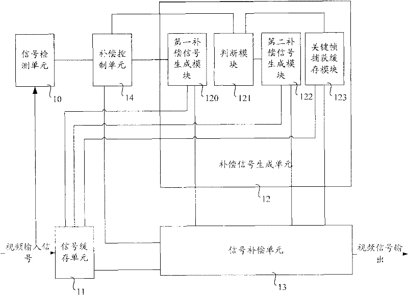
[0025] According to an embodiment of the present invention, a video signal compensation device is provided, figure 1 is a schematic structural diagram of a video signal compensation device according to an embodiment of the present invention, such as figure 1 As shown, the video signal compensation device according to the embodiment of the present invention includes: a compensation signal generation unit 12 and a signal compensation unit 13 . Preferably, the video signal compensation device in the embodiment of the present invention may further include a signal detection unit 10 , a signal buffer unit 11 , and a compensation control unit 14 .

[0026] Wherein, the signal detection unit 10 is used for detecting the video input signal, and the detected quality data about the video input signal will be...


PUM


Abstract

The invention provides a video signal compensating method, device and system. The video signal compensating method comprises the following steps: acquiring a compensating signal based on a cached video signal, when the fact that a video input signal has signal loss is detected; and inserting the compensating signal in the video input signal. Through the above processing steps, video signals whichare interrupted frequently and transiently can be effectively compensated, thus ensuring complete, continuous and stable video signal output, providing excellent subjective experience for audiences, and preventing a coder from being impacted by coding streams interrupted frequently when being applied to the coder sensitive to input video signals.

Description

technical field [0001] Embodiments of the present invention relate to the technical field of video signals, and in particular, to a video signal compensation method, device and system. Background technique [0002] In related technologies, abnormalities in the video acquisition process (for example, the magnetic powder of the recording signal tape falls off), attenuation in the transmission process, or interference with the transmission channel (for example, a large clock offset or jitter occurs in the transmission process) Etc., all will cause line signal loss and / or frame (also called field) signal loss in the video signal, and may even cause a long-term interruption of the video signal in severe cases. [0003] In the prior art, the video encoding device has strict requirements on the format of the input signal, and each encoding device can only encode the video signal of the specified format, wherein, the above-mentioned video signal format refers to: the image resolutio...

Claims


Application Information

Patent Timeline
Patent Type & Authority Patents(China)
IPC IPC(8): H04N7/64H04N19/89
Inventor 朱雄羽彭非
Owner XFUSION DIGITAL TECH CO LTD
Learn More