
V-shaped vertical windmill

A windmill and vertical technology, applied in the energy field of wind energy utilization, can solve the problem of wind wheel enlargement

Inactive Publication Date: 2011-07-13
李永平
View PDF0 Cites 7 Cited by
  • Summary
  • Abstract
  • Description
  • Claims
  • Application Information

AI Technical Summary

Problems solved by technology

[0005] After research, the inventor believes that the use of a V-shaped wind wheel can effectively solve the problem of avoiding the use of tall central shafts or tall columns, while making the wind wheel bigger

Method used


Image

  • V-shaped vertical windmill
  • V-shaped vertical windmill
  • V-shaped vertical windmill

Examples


example 1 3

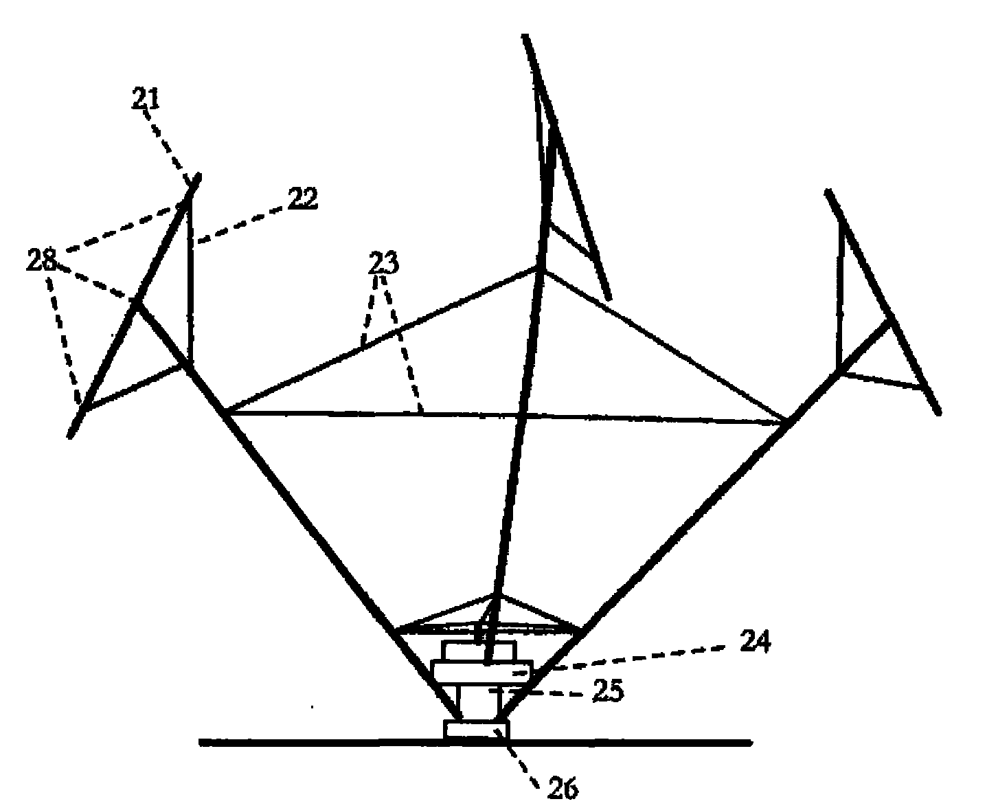
[0034] Example 1 Three-bladed V-type vertical wind wheel

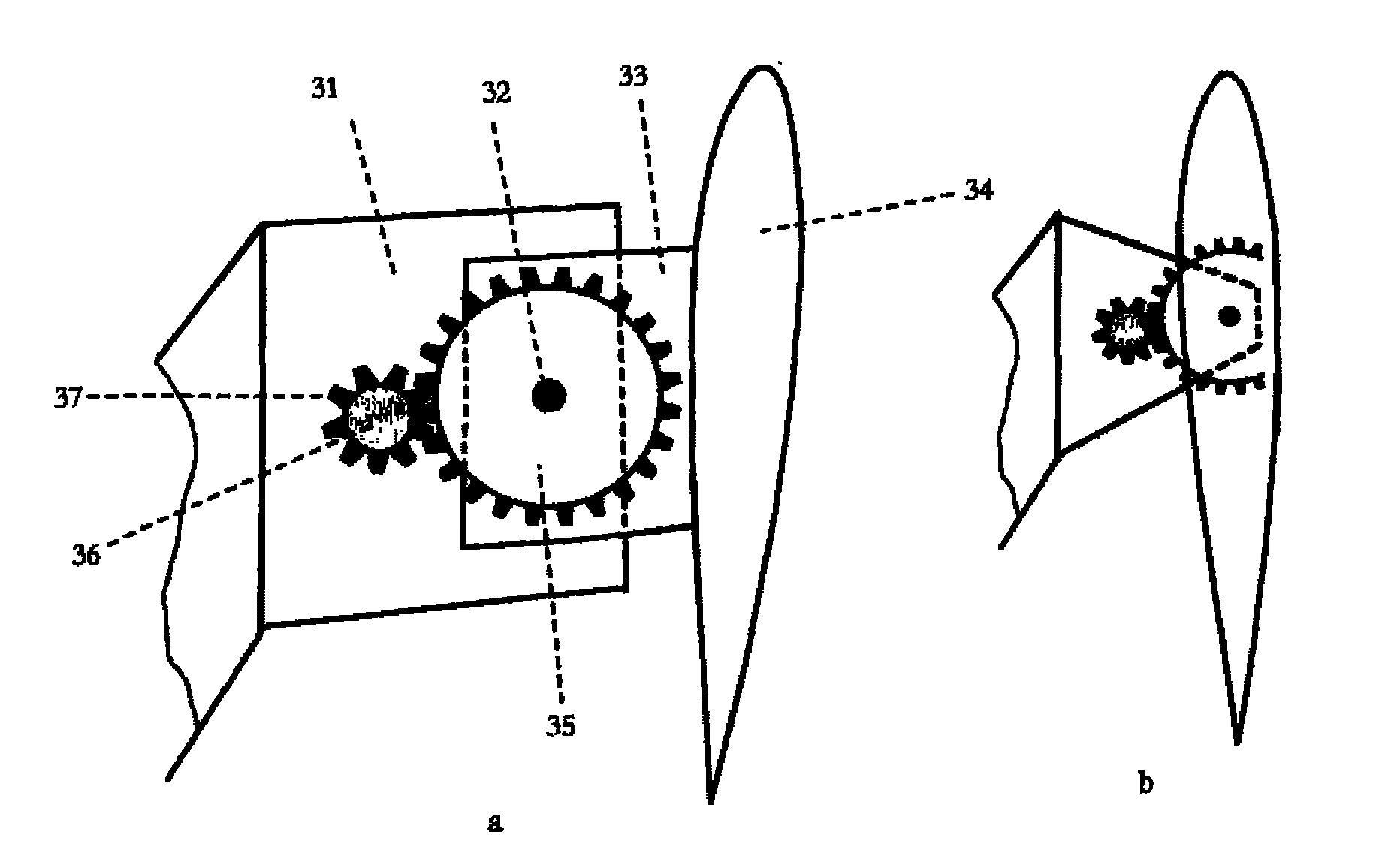
[0035] Its appearance and shape are as attached figure 2 shown. Its structural principle is as attached figure 1 , attached figure 2 , attached image 3 , attached Figure 4 shown.

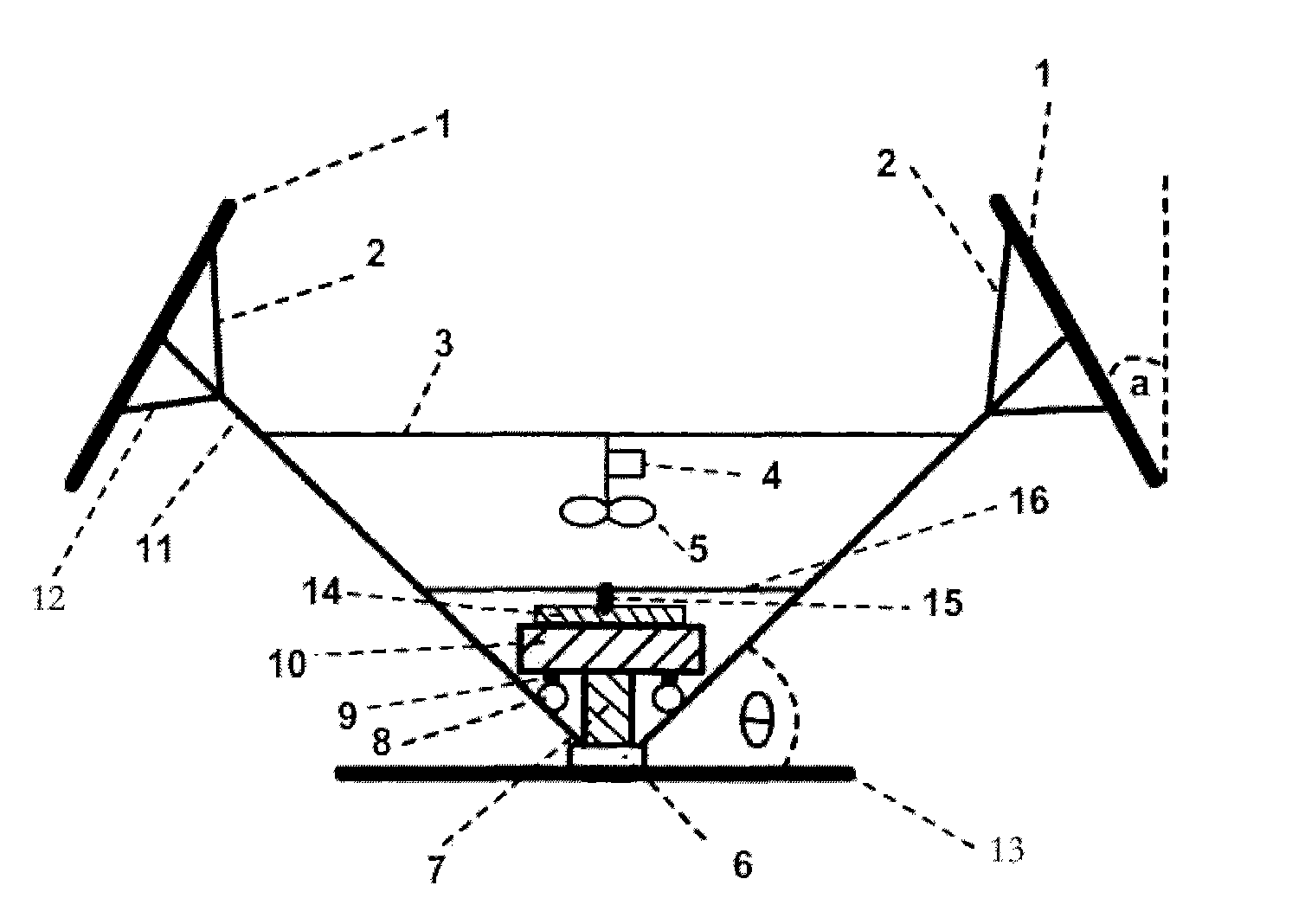
[0036] The wind wheel has the following figure 1 The oblique support arm 11 shown in , the angle θ between the support arm and the horizontal plane is 30-75 degrees, the auxiliary support arm 2 is installed on the support arm 11, and the inwardly inclined blade 1 is installed on the top end, the blade 1 The angle a with the vertical direction is 1 to 45 degrees. The lower end of the support arm is installed on a rotatable base 6, and a column 7 of a T-shaped column is installed in the base 6, so that the support arm can rotate around the column 7, T The shaped column is composed of a column 7 and a disc 10. On the lower plane of the disc 10, a ring rail 9 is installed, and at the position corresponding to the support arm and the r...

example 2

[0037] Example 2 The V-type vertical windmill when the generator replaces the T-shaped column

[0038] attached Figure 5 A schematic diagram of a 3-bladed V-shaped vertical windmill is shown. in the attached Figure 5 Among them, the connection 51 between the blade and the support arm is fixedly connected, and a disc generator is used. The blade support arm is installed on a rotatable base 55, and the generator rotor 53 is connected with the rotating base 55 and is located on the 55. The generator The stator 52 is installed on the rotor, and is connected with the base 54 through the shaft, and is fixed together. The windmill is a small windmill, so only two supporting points are provided between the blades and the support arms.

example 3

[0039] Example 3 V-type vertical windmill using "<" type blades and C-type blades

[0040] attached Figure 6 It is a schematic diagram of a V-shaped vertical windmill using " Figure 7 It is a schematic diagram of a V-shaped vertical windmill using C-shaped blades, and the connection between the blades and the support arm is fixedly connected.


PUM


Abstract

The invention relates to a V-shaped vertical windmill which is mainly composed of a rotatable base seat, primary fan blade supporting arms, auxiliary supporting arms, horizontal connecting rods, a T-shaped column, fan blades, a coupler, a generator, a speed changing box and the like, wherein the primary supporting arms are inclined upwards; the auxiliary supporting arms are arranged on the primary supporting arms; the horizontal connecting rods are connected among the primary supporting arms; a wind wheel is provided with a plurality of primary supporting arms which are inclined upward and form an angle of 30-75 degrees with the water level, so that the whole wind wheel presents a V shape; the fan blades are installed at the top ends of the primary supporting arms; a V-shaped bottom part is used as a fulcrum of the rotation of the windmill; the supporting arms are connected by the horizontal connecting rods for strengthening; the swing of the windmill is controlled by one T-shaped column; the generator, the speed changing box and the like are positioned on a T-shaped column disk, and the weight of the T-shaped column disk is increased by fully utilizing the weights of the generator and the speed changing box; the spreading direction of the fan blades and the vertical direction form an included angle of 0-45 degrees; and the attack angles of the fan blades are regulated by a servo motor and a hydraulic device which are controlled by a computer.

Description

[0001] Field [0002] The invention relates to a V-shaped vertical windmill, which belongs to the energy field of wind energy utilization. technical background [0003] The existing large-scale vertical axis wind rotors used for wind power generation are usually Darrieus-type Φ-shaped wind rotors. This type of wind rotor has a simple structure, but it also has obvious defects. Because the shaft is very long, it needs to be applied by cables. The tension presses the structure to keep the wind rotor vertical, resulting in severe vibration of the wind rotor, high bearing friction, failure of self-starting and braking, etc. In order to solve the problems caused by the tall rotating shaft, people have developed the H-type wind rotor. When the support arm of the blade adopts the triangular vector support form, the long rotating shaft can be omitted. Its characteristic is that the rotation fulcrum of the wind rotor is generally located in the center of the wind rotor Therefore, this...

Claims


Application Information

Patent Timeline
IPC IPC(8): F03D3/06F03D11/00F03D7/06F03D13/20
CPCY02E10/72Y02E10/74
Inventor 李永平
Owner 李永平
Learn More