
Image measuring method for compression quantity of tyre and axle displacement in drop test

A technology of image measurement and compression, which is applied in the direction of measuring device, impact test, machine/structural component test, etc., can solve the problems of not being able to adapt to mechanical shock and installation difficulties, and achieve the effect of avoiding impact and installation difficulties

Active Publication Date: 2011-07-13
JIANGXI HONGDU AVIATION IND GRP
View PDF1 Cites 24 Cited by
  • Summary
  • Abstract
  • Description
  • Claims
  • Application Information

AI Technical Summary

Problems solved by technology

[0005] The purpose of the present invention is to overcome the shortcomings of the existing technology that cannot adapt to mechanical shock and difficult installation, and provide an image measurement method for measuring tire compression and wheel axle displacement

Method used


Image

  • Image measuring method for compression quantity of tyre and axle displacement in drop test
  • Image measuring method for compression quantity of tyre and axle displacement in drop test
  • Image measuring method for compression quantity of tyre and axle displacement in drop test

Examples


Embodiment 1

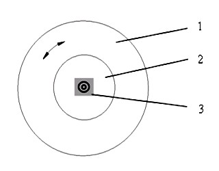
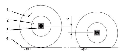
[0038] In the aforementioned specific embodiments, the camera faces the side of the tire and the positioning mark 3, that is, the optical axis of the camera lens is perpendicular to the side of the wheel, and is as close as possible to the wheel axle, so that the motion plane of the positioning mark 3 is basically parallel to the imaging plane of the camera, and the positioning mark 3 The range of motion is in the center of the image, such as Figure 6 ;Although the camera can be calibrated and measured if it is not facing the side of the tire, it is more conducive to improving the measurement accuracy if it is facing the side of the tire.

Embodiment 2

[0040] In the aforementioned specific embodiments, the position of the positioning mark 3 is set at the center of the axle on the side of the wheel.

Embodiment 3

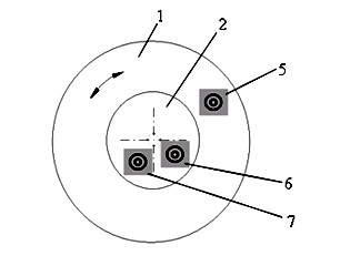
[0042] In the aforementioned specific embodiments, the location of the positioning mark 3 is most ideally set at the center of the wheel axle. When the landing gear is a strut type landing gear, and the influence of the bending deformation of the strut of the landing gear is negligible, it can be set on the non-rotatable part of the wheel. Any location, but the closer to the center of the axle the better.


PUM


Abstract

The invention discloses an image measuring method for compression quantity of a tyre and an axle displacement in a drop test. The axle displacement is obtained by the steps of arranging a mark pattern on an axle, acquiring high-speed photographic images of a wheel during moving, and tracking and positioning marks in each frame image, and the compression quantity of the tyre is obtained by simple calculation. In the image measuring method, the marks arranged on the axle are used as measuring objects, high-speed photographic digital images of the machine wheel and the marks are captured by a high-speed camera in the drop test, and impact of the motion of the machine wheel on a measuring device and difficulty in installation are avoided due to non-contact measuring.

Description

technical field [0001] The invention relates to an image measurement technology, which is used for measuring tire compression and axle displacement in an aircraft landing gear drop test, in particular to an image measurement method for tire compression and axle displacement in a drop test. Background technique [0002] Wheels and tires are extremely important components to ensure the safety of aircraft takeoff and landing. In the drop test of aircraft landing gear, it is necessary to measure the compression of the wheel tire. [0003] The drop test simulates the landing process of the aircraft. During the test, the wheels are pre-rotated and dropped from a certain height with the landing gear. Due to the existence of the rotational inertia of the wheel, the moment the tire touches the ground, it is violently impacted by the friction force of the ground, and the landing gear strut is instantly bent and deformed. Under the action of the strut elastic force, the wheel vibrates...

Claims


Application Information

Patent Timeline
IPC IPC(8): G01B11/03G01M7/08
Inventor 刘群根万健平孙福强
Owner JIANGXI HONGDU AVIATION IND GRP
Learn More