Vertically taking off and landing small unmanned aerial vehicle

A small unmanned aerial vehicle, vertical take-off and landing technology, applied in the direction of rotorcraft, motor vehicles, aircraft control, etc., can solve the problems of small flight range, poor take-off and landing conditions, low flight speed, etc., and meet the requirements of reducing the take-off and landing space , Expand the scope of use, and the effect of good application prospects

Inactive Publication Date: 2011-07-20
BEIHANG UNIV
View PDF7 Cites 68 Cited by
  • Summary
  • Abstract
  • Description
  • Claims
  • Application Information

AI Technical Summary

Problems solved by technology

However, unmanned helicopters have complex structures, high maintenance requirements, high failure rates, low flight speeds, and short voyages.
[0005] In many applications, even the most basic take-off and landing site requirements are difficult to meet, which greatly limits the scope of use of fixed-wing UAVs
Taking the disaster assessment task in the earthquake area as an example, at the initial moment of the earthquake, the road was damaged, and external personnel could not quickly enter the earthquake area to understand the loss situation
However, in order to provide relevant departments with the ba

Method used


Image

  • Vertically taking off and landing small unmanned aerial vehicle
  • Vertically taking off and landing small unmanned aerial vehicle
  • Vertically taking off and landing small unmanned aerial vehicle

Examples


specific example

[0042] The embodiment of the present invention is described below by two kinds of examples:

example 1

[0043] Example 1: Conversion between vertical take-off and landing and horizontal flight

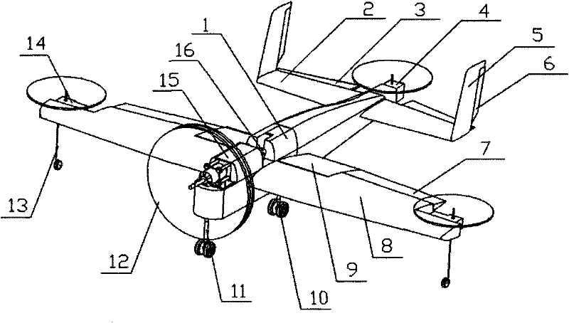
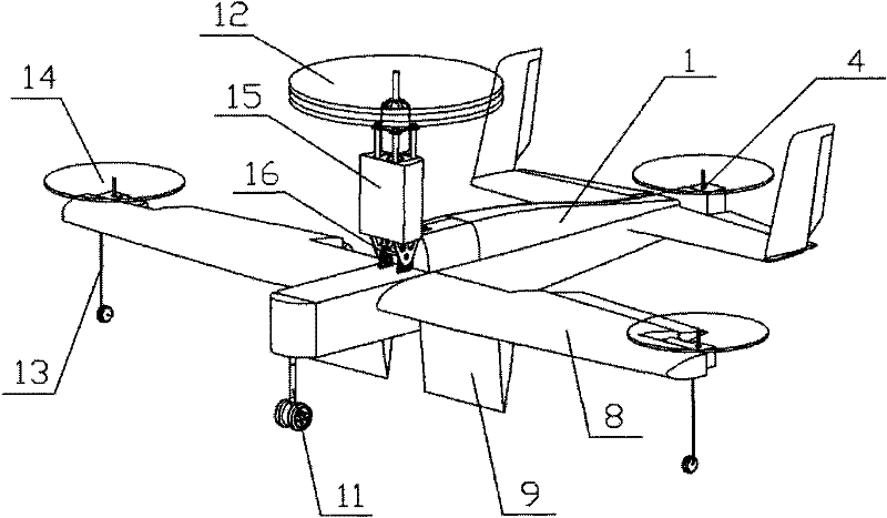
[0044] When the take-off and landing conditions are good, carry out horizontal taxi take-off and landing. When the take-off and landing environment is too bad to take off and land horizontally, the power cabin of the nose is tilted to a vertical state, the attitude adjustment system is turned on, and the vertical take-off is carried out. After reaching a certain height, the power cabin of the nose slowly turns to a horizontal state. After the horizontal flight speed accumulates to a certain flight speed, turn off the attitude adjustment system and switch to normal horizontal flight. After completing the flight mission, reach the sky above the landing area, turn on the attitude adjustment system, and the power cabin of the nose will slowly tilt to a vertical state, and after the flight speed drops to zero, it will land vertically.

example 2

[0045] Example 2, horizontal flight and hovering in the air conversion

[0046] When performing tasks that require hovering in the air, such as aerial photography, after the aircraft flies horizontally to the sky above the target, the attitude adjustment system is turned on, and the power cabin of the nose is tilted to be perpendicular to the ground, and it is converted into a hovering state in the air. Carry out fixed-point aerial photography and detection. After completing the mission, the power cabin of the nose is tilted to a horizontal state. After accumulating to a certain flight speed, the attitude adjustment system is turned off, converted to a horizontal flight state, and flies away from the target.


PUM


Abstract

The invention relates to an unmanned aerial vehicle which can vertically take off and land and hover in the air and has higher flight speed and larger flying range. The unmanned aerial vehicle does not need running take-off, thereby reducing the requirement on a taking off and landing field and greatly expanding the application range, and the unmanned aerial vehicle has higher speed and further flaying range than a manned helicopter. The unmanned aerial vehicle comprises a body (1), wings (8), a horizontal empennage (2), a vertical empennage (5), a nose power cabin (15) arranged on the front part of the body (1), a propeller power system (12) arranged on the front part of the nose power cabin (15) and a tilting mechanism (16) arranged on the middle upper part of the body, wherein the nosepower cabin (15) is connected with the body in a titling mode through the tilting mechanism (16) so as to ensure that the axial directions of the propellers (121) and (122) of the propeller power system (12) can be correspondingly titled.

Description

technical field [0001] The invention relates to a small unmanned aerial vehicle with a vertical take-off and landing function, which belongs to the field of aviation vehicle design. Background technique [0002] Unmanned aircraft, referred to as UAV, is a powered, unmanned, reusable or one-time use aircraft. UAVs are often classified by weight, of which less than 20kg are called micro or small UAVs, which are generally used to perform military tasks such as battlefield reconnaissance, damage assessment, and target guidance, as well as as a carrier platform for flight tests and aerial surveying and mapping. and other non-military tasks. [0003] Small fixed-wing UAVs generally adopt horizontal taxi takeoff, hand throw takeoff, catapult takeoff and other forms of take-off, and usually adopt taxi landing, parachute landing and other forms of landing. Hand-throwing and catapult take-off are limited by the strength of the personnel's arms and the thrust of gunpowder and springs...

Claims


Application Information

Patent Timeline
IPC IPC(8): B64C27/08B64C27/12B64C27/52B64C9/00B64C5/02B64C25/02
Inventor 万志强王耀坤雷萤王川周磊
Owner BEIHANG UNIV
Why Eureka
Try Eureka